Light-guide optical element and method of its manufacture

Active Publication Date: 2018-10-11
LUMUS LTD
View PDF1 Cites 49 Cited by
  • Summary
  • Abstract
  • Description
  • Claims
  • Application Information

AI Technical Summary

Problems solved by technology

To this end, the actual active area of each partially reflecting surface is to be considered, because a potential non-uniformity in the resulting image might occur due to the different reflection sequences of different rays that reach each selectively reflecting surfaces.
Therefore, if overlapping is set between the reflective surfaces to compensate for the inacti

Method used


Image

  • Light-guide optical element and method of its manufacture
  • Light-guide optical element and method of its manufacture
  • Light-guide optical element and method of its manufacture

Examples


Embodiment Construction

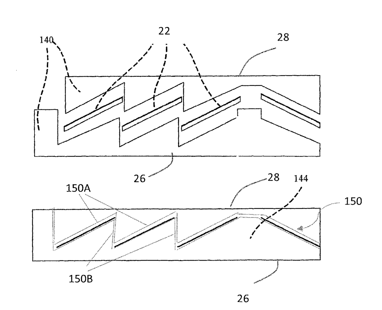
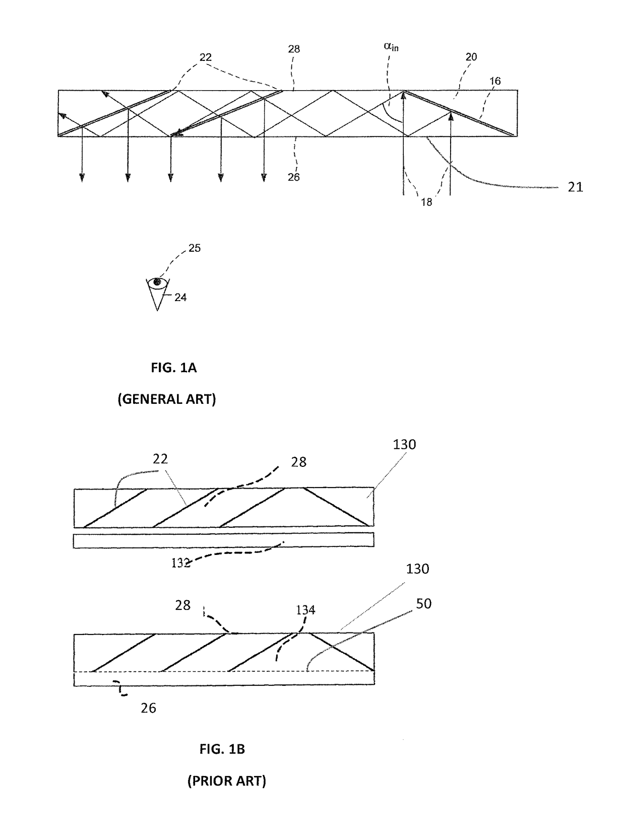
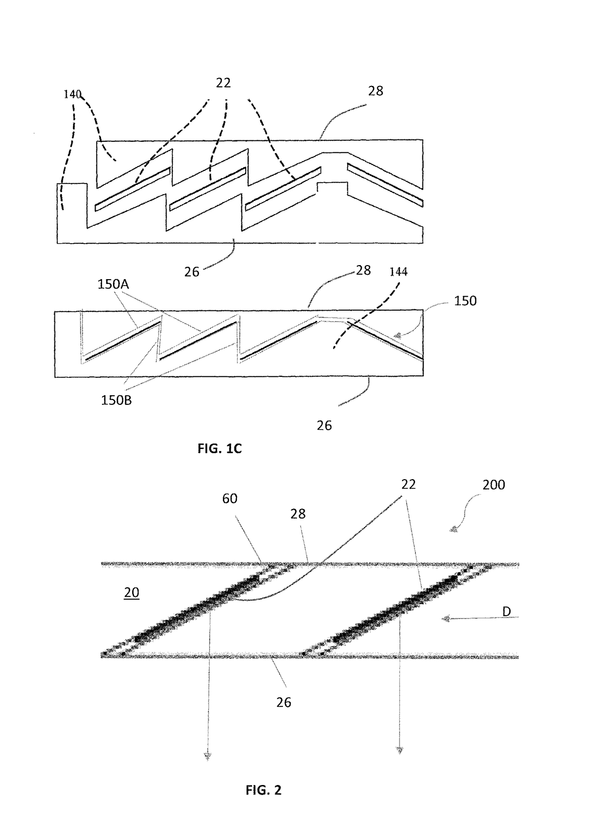
[0054]As described above, FIG. 1A illustrates schematically the configuration and operation (light propagation scheme) in a conventional LOE device, and FIGS. 1B and 1C show two examples of the improved LOE configuration providing that the light directing surfaces are fully embedded in substrate of the LOE device, being spaced from the major surface(s) thereof.

[0055]Reference is now made to FIG. 2 which schematically illustrates a part of an LOE device 200 configured according to the present invention. To facilitate understanding, the same reference numbers are used for identifying components that are common in all the examples of the invention and those of the known device described above.

[0056]The LOE 200 includes an optically transparent body 20 which has two major surfaces 26 and 28 and one or more light directing surface 22. The LOE's is thus configured for guiding input light in a general propagation direction D through the body by total internal reflections of light from the ...


PUM


Abstract

An optical structure and corresponding process of manufacture for light guide optical elements (LOEs) which guide light by reflection at major surfaces. The structure further includes light directing surfaces for coupling light out of the LOE, obliquely inclined with respect to the major surfaces. The optical structure is formed from a stack of multiple optically transparent layers each of which has a surface pattern of regions configured as light directing surfaces which are arranged in an X-Z plane in a spaced-apart relationship along at least the X-axis with optically transparent regions between them. The layers are stacked along a Y-axis so that each of the surface patterns is located at an interface between two adjacent layers and the patterns of the layers are aligned with a shift of a predetermined value along one or both of the X-axis and Z-axis.

Description

TECHNOLOGICAL FIELD AND BACKGROUND[0001]The present invention is in the field of optical devices and relates to a compact light-guide optical element and a method of its manufacture. More specifically, the present invention relates to a substrate-guided optical device including one or more at least partially reflecting or diffractive surfaces carried by a common light-transmissive substrate.[0002]Such light-guide optical element (LOE) can be used in a large number of imaging applications, such as portable DVDs, cellular phone, mobile TV receiver, video games, portable media players, or any other mobile display devices, e.g. see-through near-eye display, or head-mounted display, for use in augmented / virtual reality systems. The main physical principle of the operation of LOE is that light waves are trapped inside a substrate by total internal reflections from the major surfaces of the LOE. In addition, the light waves which are trapped inside the LOE are coupled out into the eyes of ...

Claims


Application Information

Patent Timeline
IPC IPC(8): F21V8/00
CPCG02B6/0076G02B6/0055G02B6/0058G02B6/0065G02B5/3083G02B6/0056G02B27/0081G02B27/0172G02B27/283G02B27/285G02B5/30G02B5/28G02B6/0035G02B2027/0116G02B2027/0123G02B2027/0174G02B27/1073G02B27/145G02B6/0036
Inventor OFIR, YUVALFRIEDMANN, EDGARBITAN, MEIR TZION
Owner LUMUS LTD
Why Eureka
Try Eureka