
Compact eye imaging and eye tracking apparatus

a technology applied in the field of eye imaging and eye tracking devices, can solve the problems of unsightly appearance, test subjects are unlikely to use tobii products outside of the laboratory environment, and the design is not easy to be seen, and achieves the effect of superior optical quality and minimal distortion

Active Publication Date: 2016-05-24
AUGMENTED VISION
View PDF65 Cites 54 Cited by
  • Summary
  • Abstract
  • Description
  • Claims
  • Application Information

AI Technical Summary

Benefits of technology

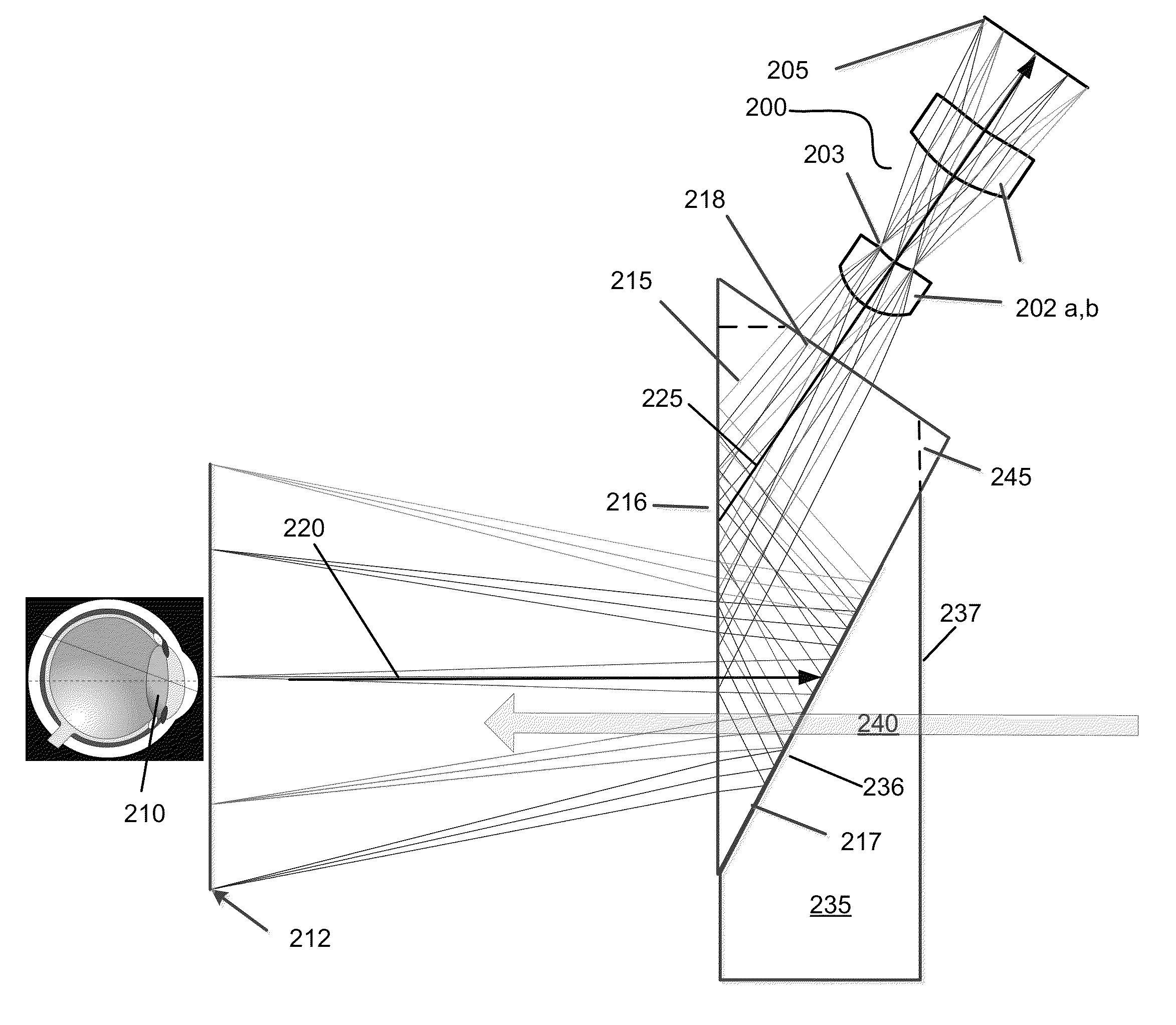
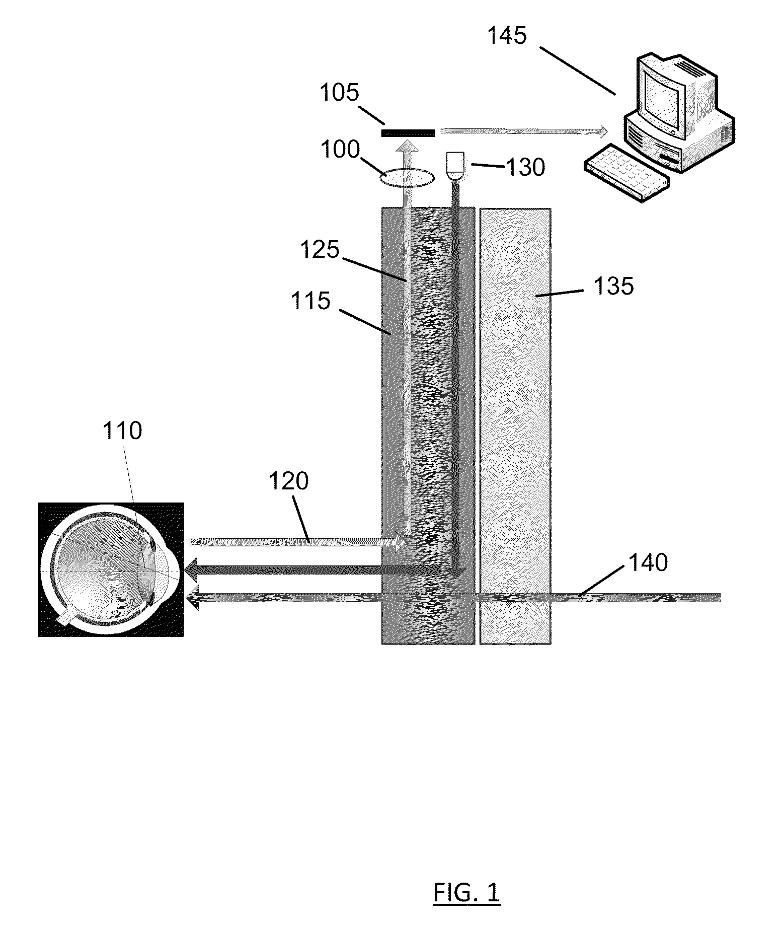
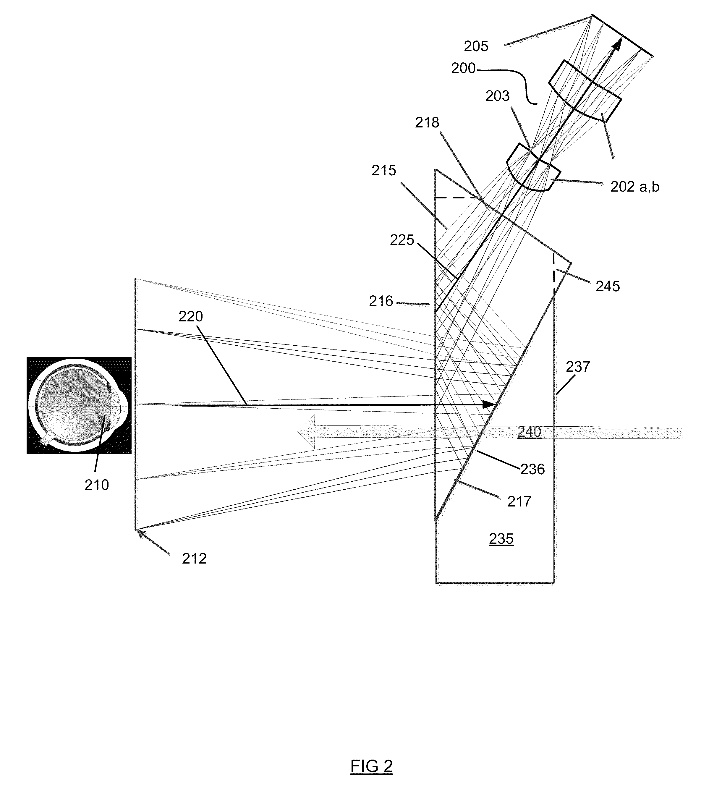
The present invention is about an optical device that can capture eye images and track eye gaze direction. The device is compact, lightweight, and has a see-through capability that allows the observer to view the surrounding environment with minimum distortion and superior optical quality. The invention uses a thin prism between the eye and a camera system, which acts as a light-guide and optionally folds an illumination path between the illumination source and the eye. The invention also includes a corrective optical element to eliminate any deviation or aberrations in the see-through viewing path introduced by the thin prism. Overall, the invention provides a thin, eyeglass-like eye tracking device that captures a frontal or near frontal image of the eye at a distance while maintaining a light-weight, visually appealing form factor.

Problems solved by technology

This approach results in a bulky design and an unsightly appearance, which potentially may comprise research results.
The resulting overall package does not resemble a conventional pair of eyeglasses, and as a result, test subjects are unlikely to use the Tobii product outside of a laboratory environment.
This results in a thick and bulky frame design, which must move the camera far enough away from the face to avoid interference.
Furthermore, in this system, the camera captures an eye image at a close distance and from a slanted direction (i.e., at a high angle), which results the eye image suffering keystone distortion.
This arrangement also presents optical performance challenges due to the large depth of field necessary to accommodate all possible eye positions.
While the arrangement of this patent is an improvement over other designs discussed above, the field of view of the camera in this arrangement is severely limited by the disclosed geometry.
The camera images an eye using a bulky and unsightly visor that hangs in front of the face of a user.
While this device appears to be somewhat similar to a pair of eyeglasses in form factor, it is necessarily expensive and complex to fabricate, as it requires the use of semi-conductor fabrication processes to fabricate optical detectors and their associated electronics on a curved glass lens substrate.

Method used


Image

  • Compact eye imaging and eye tracking apparatus
  • Compact eye imaging and eye tracking apparatus
  • Compact eye imaging and eye tracking apparatus

Examples


Embodiment Construction

[0042]The invention is described in preferred embodiments in the following description with reference to the Figures, in which like numbers represent the same or similar elements. Reference throughout this specification to “one embodiment,”“an embodiment,” or similar language means that a particular feature, structure, or characteristic described in connection with the embodiment is included in at least one embodiment of the present invention. Thus, appearances of the phrases “in one embodiment,”“in an embodiment,” and similar language throughout this specification may, but do not necessarily, all refer to the same embodiment.

[0043]The described features, structures, or characteristics of the invention may be combined in any suitable manner in one or more embodiments. In the following description, numerous specific details are recited to provide a thorough understanding of embodiments of the invention. One skilled in the relevant art will recognize, however, that the invention may b...


PUM


Abstract

An optical system for eye tracking is disclosed. The system includes a light guiding prism that guides light from an ocular object to an imaging system through multiple internal reflections. The light guiding prism may include one or more freeform surfaces having optical power.

Description

CROSS REFERENCE TO RELATED APPLICATIONS[0001]This application claims priority to U.S. Provisional Patent Application No. 61 / 699,462, filed on Sep. 11, 2012 and U.S. Provisional Patent Application No. 61 / 736,832, filed on Dec. 13, 2012, the disclosures of which are incorporated herein by reference in their entirety.FIELD OF THE INVENTION[0002]The present invention relates generally to eye imaging and eye tracking devices, and more particularly, but not exclusively, to a compact eye-glass-like wearable optical device that is capable of capturing an eye image and tracking eye gaze direction.BACKGROUND OF THE INVENTION[0003]Eye tracking is the process to measure the eye movement or the eye-gaze direction. Various eye tracking technologies have been developed for use in a variety of applications, such as vision research, human computer interfaces, tele-surgery, product packaging, retail layout and advertising research, visual communication, and various military applications. One conventi...

Claims


Application Information

Patent Timeline
Patent Type & Authority Patents(United States)
IPC IPC(8): A61B3/14A61B3/10G02B27/14A61B3/113G06K9/00
CPCA61B3/113G06K9/00604G06V40/19A61B3/0025A61B3/14G02B5/04G02B5/0825G02B17/0856G02B27/0025
Inventor GAO, CHUNYU
Owner AUGMENTED VISION
Learn More