
Polarized optical part using high impact polyurethane-based material

a polyurethane-based material and polarized optical technology, applied in the direction of polarising elements, instruments, spectales/goggles, etc., can solve the problems of inability to adjust the polarization angle, and heavy weight of polymeric thermoset resins such as cr-39®, so as to improve the polarization angle. , the effect of high optical quality

Inactive Publication Date: 2006-02-21
YOUNGER MFG
View PDF46 Cites 51 Cited by
  • Summary
  • Abstract
  • Description
  • Claims
  • Application Information

AI Technical Summary

Benefits of technology

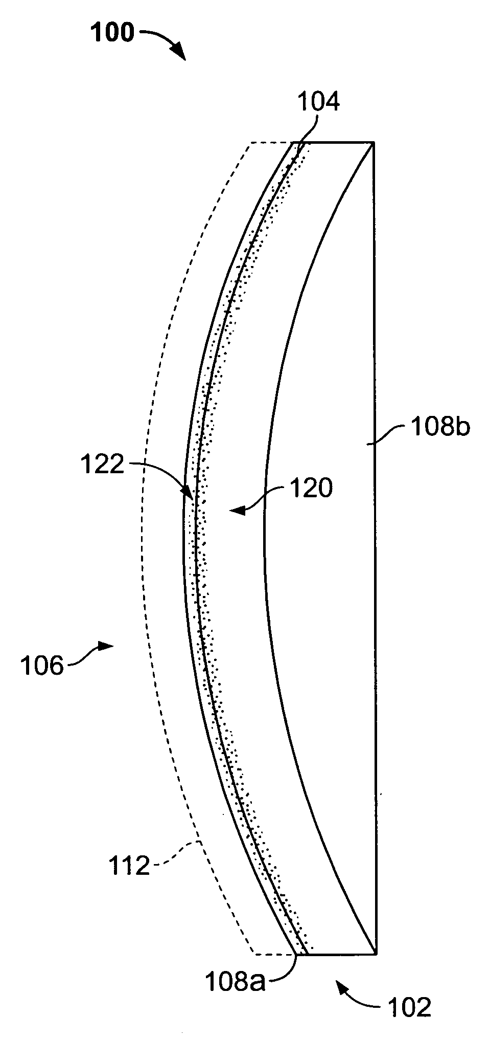
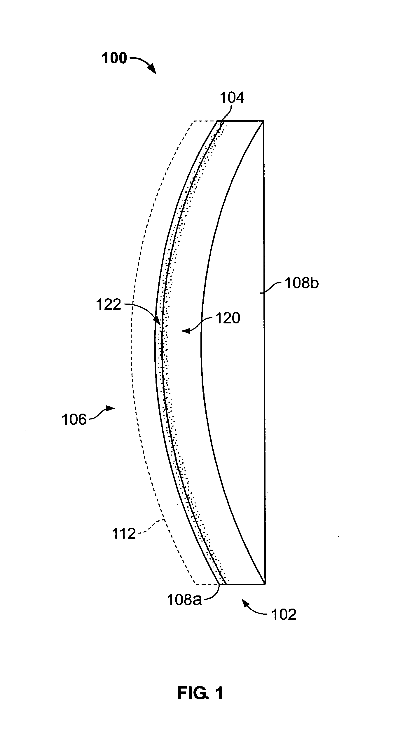
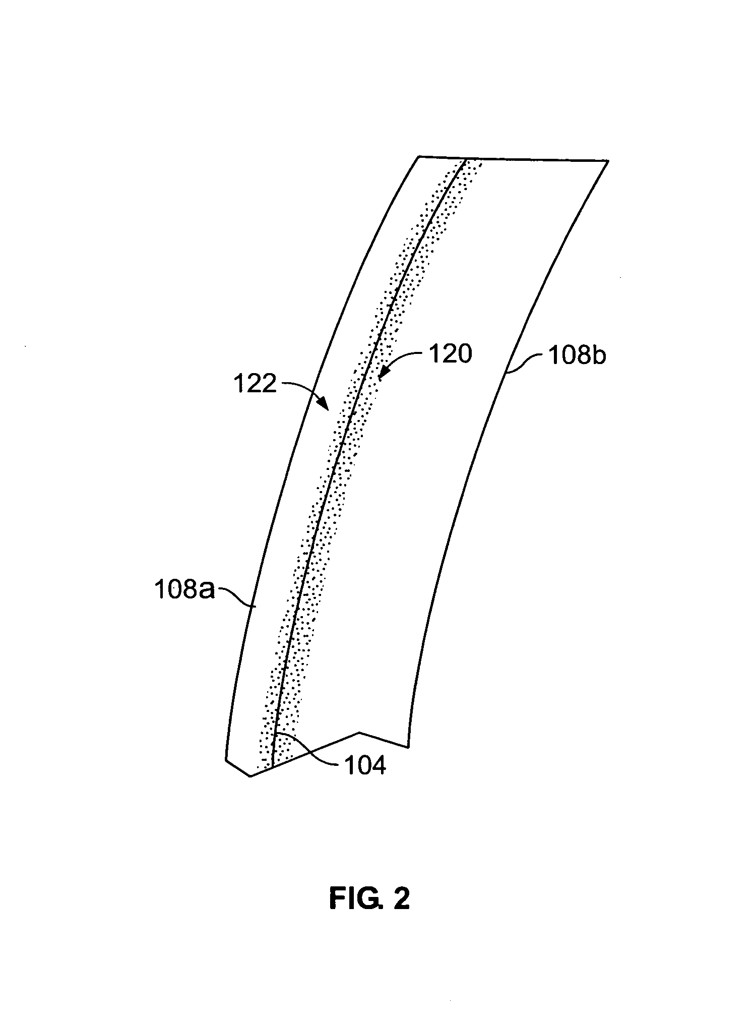
[0013]The preferred embodiments relate to optical-quality polarized parts and to methods of manufacturing such optical parts comprising a high impact, lightweight, high optical quality polyurethane-based material and a polarizer. The polarized optical part advantageously has improved impact resistance over conventional thermoset resin parts, as well as better optical properties than similarly impact-resistant polycarbonate constructs.

Problems solved by technology

Most often, however, the respective properties of different materials necessitate trade-offs among the desired lens characteristics.
For instance, glass has very good optical properties, but it is heavy (a dense material) and only impact resistant if thick (resulting in an even heavier lens).
Polymeric thermoset resins, such as CR-39®, are lighter in weight but are lacking in impact resistance.
However, polycarbonate exhibits more chromatic aberration than glass, typically resulting in unacceptable off-axis distortion.
While this material may offer improved lens characteristics over conventional materials, the inventors noted that it has too much residual yellowness for an acceptable standard ophthalmic lens.
In addition, when the inventors worked with the disclosed prototype material to try to manufacture lenses, they noted that it does not have sufficient structural integrity to maintain an accurate optical power when surfaced with standard optical grinding, polishing, and edging techniques.
The result is that the lens will be far superior to a tinted lens in blocking glare (since tinted lenses have no preferential absorption or reflection for plane polarized glare), but it will also not be as efficient as a lens without birefringent materials.
Initial tests, however, led the inventors to believe that their modified high impact polymeric material could not be utilized to manufacture optical-quality polarized plastic parts.
Thus, initial testing revealed that a substitution of their high impact material for standard lens thermoset resin materials and conventional manufacturing processes was not possible.
Analysis of the initial testing further revealed that the properties of their modified high impact polymeric material greatly contributed to the inventors' failure to incorporate it into an improved optical-quality, polarized plastic part.
However, their modified high impact polymeric material solidifies more quickly than standard thermoset resins (approximately 30 seconds rather than several hours).
The modified high impact polymeric material creates considerable heat within the mold assembly during its normal, exothermic curing process.
This can soften the polarizer or supporting layers, causing further displacement of the polarizing film.
Depending on the polarizers or polarizing materials used, this heat could also change the color or decrease the efficiency of a polarizer.
Organic dyes used as polarizers would be especially susceptible to this type of damage.
Thus, the inventors recognized that existing manufacturing processes suggested that high impact polyurethane-based material could not be used to effect an optical-quality plastic part due to the fundamental difficulty of handling the fast-reacting modified high impact polymeric material, in combination with the more demanding process of reproducibly positioning a polarizer within any optical construct, while maintaining the optical and mechanical performance of the part.

Method used


Image

  • Polarized optical part using high impact polyurethane-based material
  • Polarized optical part using high impact polyurethane-based material
  • Polarized optical part using high impact polyurethane-based material

Examples


example 1

[0078]A conventional thermoset mold cavity was assembled with a PVA polarizer film mounted within the lens cavity. High impact polyurethane-based material was introduced into the cavity and allowed to flow around the polarizer. The lens was allowed to solidify at room temperature for a duration less than 10 minutes (until mixture gels). The lens was allowed to continue its reactive cure at 121 C for 16 hours.

[0079]

RESULTS:Polarizer typeDisplacement of polarizer?Adhesiona. PVA polarizer film,Yes-unacceptable   treated for adhesion

example 2

[0080]This example is representative of the manufacturing method illustrated in FIG. 3. A thermoset mold cavity was assembled with the polarizer resting against the front mold surface. Using a sidefill gasket design as disclosed in U.S. Pat. No. 6,391,231, wherein the gasket has vent holes in addition to a filling port, liquid-phase polyurethane-based material was admitted to only the region of the assembly behind the polarizer film. The lens was allowed to solidify at room temperature for a duration less than 10 minutes (until mixture gels). The lens was placed in an oven to continue its reactive cure at 121° C. for 16 hours.

[0081]

RESULTS:DisplacementPolarizer typeof polarizer?Adhesiona. PET polarizer film UVNoDelaminated with edge treated on back surface onlypressureb. PET polarizer, untreatedNoPoorer adhesion than a.c. PC / PVA / PC waferNoYes-PASSED TEST

example 3

[0082]This example is representative of the manufacturing method illustrated in FIG. 4. A thermoset mold cavity was assembled with a polarizing layer using a sidefill gasket design as disclosed in U.S. Pat. No. 6,391,231. Specifically, a slot-shaped port hole acted as the fill port to introduce, in a controlled manner, the thermosetting resin material along the edge axis of the embedded layer. Two port holes functioning as vent holes were located above the edge axis of the embedded material, i.e., on the thinner side of the lens to allow egress of any gases from the front surface of the lens. An additional vent port was located below the edge axis of the embedded material on the thicker side of the lens to allow egress of any gases from the back lens surface. A curved fill nozzle designed to match the slot-shaped fill port was used to introduce material into the cavity around the polarizing layer until the cavity was full and a small amount of material flowed out of the egress holes...


PUM

PropertyMeasurementUnit
weight average molecular weightaaaaaaaaaa
molar percentaaaaaaaaaa

Abstract

Optical-quality polarized parts and methods for manufacturing the optical parts are disclosed. The optical-quality polarized parts comprise a high impact, lightweight, high optical quality polyurethane construct and a polarizer bonded to the construct. The construct may be a lens substrate wherein the polarizer is integrally bonded at or near the front surface of the lens substrate. A sidefill gasket may be used to support and position the polarizer within a mold cavity for reproducibly forming the optical part. The polarizer may comprise a polyethylene terephthalate film or a laminated polyvinyl alcohol film or wafer. The polarized optical part has improved impact resistance over conventional thermoset resin parts, as well as better optical properties than similarly impact-resistant polycarbonate constructs.

Description

CROSS-REFERENCE TO RELATED APPLICATIONS[0001]This is a continuation-in-part of U.S. patent application Ser. No. 09 / 569,479 filed May 12, 2000; Ser. No. 09 / 567,711 filed May 10, 2000; Ser. No. 09 / 475,424 now U.S Pat. No. 6,220,703 filed Dec. 29, 1999; and Ser. No. 09 / 447,445 filed Nov. 22, 1999, each of which is hereby incorporated by reference as if fully set forth herein.BACKGROUND OF THE INVENTION[0002]The field of the present invention relates to the use of high impact, lightweight, high optical-quality polymeric material in polarized plastic parts such as eyewear.[0003]Optical-quality eyewear requires good optical performance. In the selection of lens materials for use in optical-quality eyewear, the color, weight, and safety of the material is important, as well as good optical performance. Most often, however, the respective properties of different materials necessitate trade-offs among the desired lens characteristics. For instance, glass has very good optical properties, but...

Claims


Application Information

Patent Timeline
Patent Type & Authority Patents(United States)
IPC IPC(8): G02B27/28B29C33/00B29C39/10B29C39/12B29C51/10B29D11/00B32B27/36G02B5/30G02C7/10G02C7/12
CPCB29C33/0061B29C39/10B29C39/123B29C51/10B29D11/00019B29D11/00413B29D11/00432B29D11/00528B29D11/00538B29D11/0073B32B27/36G02B5/3025G02B5/3033G02C7/12G02C7/108B29C33/0077Y10S425/808B29C2791/007B29K2995/0034G02C2202/16
Inventor EVANS, RUSSELL E.BALCH, THOMAS A.YAMASAKI, NANCY L. S.
Owner YOUNGER MFG
Learn More