Electrical connector
A technology of matching connectors and grounding layers, applied in the direction of connection, fixed connection, two-part connection device, etc., can solve the problem that the impedance matching of the ground layer 62 of the center contact cannot be realized, and achieve the effect of reducing the overall height
Active Publication Date: 2010-11-10
DDK LTD
View PDF3 Cites 0 Cited by
- Summary
- Abstract
- Description
- Claims
- Application Information
AI Technical Summary
Problems solved by technology
Therefore, for the prior art electrical connectors and connectors disclosed in Patent Documents 1 to 3, there will be a problem that impedance matching between the center contact and the ground layer 62 cannot be achieved.
Method used
View moreImage
Smart ImageViewing Examples

Examples
Embodiment Construction
Login to View More PUM
 Abstract
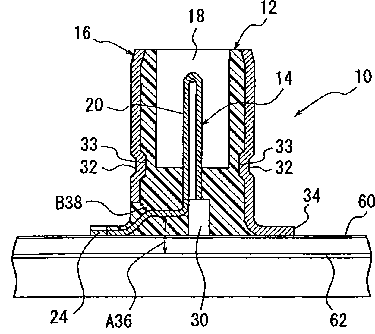
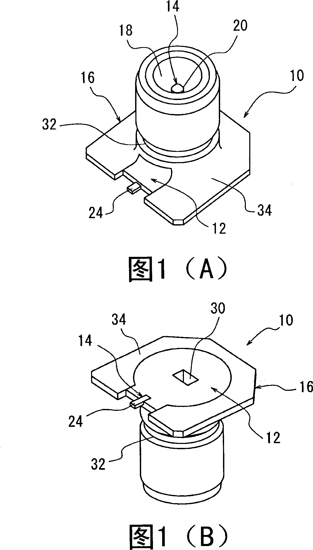
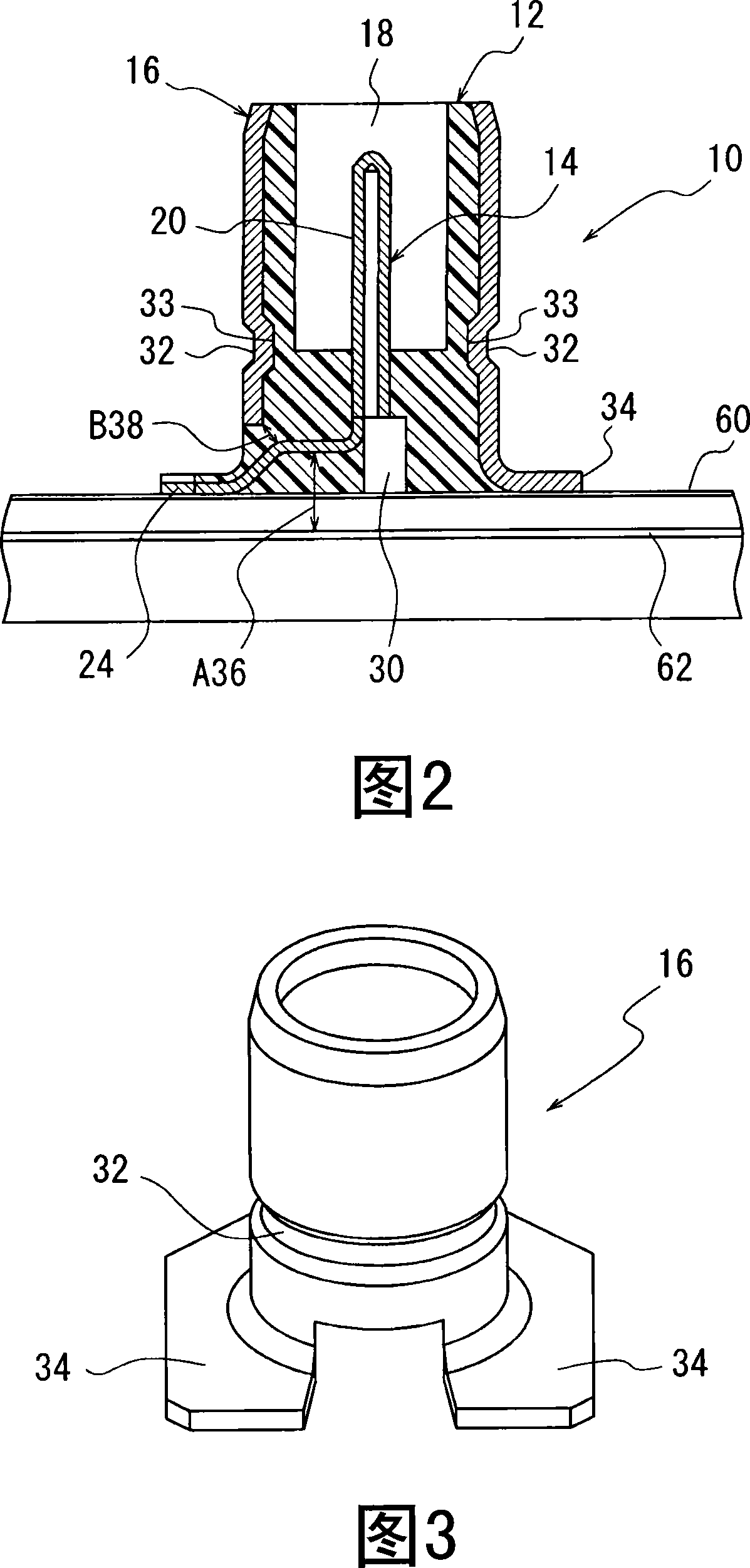
The invention provides a electrical connector, wherein, even in the circumstances that the space between a ground floor and the surface of a basement of the connector is minimum, the electrical connector can easily achieve the matching of a center contact and the ground floor of the basement as well as the impedance matching of the contact center and a external conductor, and the electrical connector can reduce the overall height and weight, the connector can be installed on two surfaces of the basement. The aim of the invention can be achieved by installing the electrical connector on the basement, the electrical connector comprises the center contact with a contact part, a maintaining part and a connecting part, a insulator and the external conductor; wherein, when the ground floor is installed into the basement, the maintaining part of the contact center is bent ,so that the contact center is roughly parallel to the surface of the basement installed with the electrical connector tomaintain the distance of the maintaining part between the ground floor and the bending between 0.5to1.5 mm, and the bending is roughly parallel to the surface of the basement, impedance matching is adjustable.
Description
Electrical connector Technical field The present invention relates to an electrical connector mounted on a base (or substrate) used in radio transceivers and measuring instruments and equipment by surface mounting, and more particularly to a grounding layer and its In the case of high-density installation, the surface of the substrate on which the electrical connector is mounted has a minimum distance between the surfaces, and an electrical connector with a structure capable of adjusting impedance matching. Background technique The electrical connector 70 used so far will be explained with reference to FIG. 5. The electrical connector 70 shown in FIG. 5 mainly includes an insulator 72, a center contact 74, and an outer conductor 76. The insulator 72 has a mounting opening 80 into which the mating connector is inserted. The center contact 74 is disposed on the insulator. 72 and held by it, the outer conductor 76 is fixed to the insulator 72 so as to cover its outer periphery, ...
Claims
Login to View More Application Information
Patent Timeline
 Patent Type & Authority Patents(China)
IPC IPC(8): H01R13/646H01R24/02H01R12/36H01R12/57
Inventor 中山佳昭
Owner DDK LTD