Surface cleaning apparatus with removable dust cup and dust removal door

A technology of surface cleaning device and dust removal door, which is applied in the direction of cleaning equipment, cleaning machinery, vacuum cleaners, etc., and can solve the problems of dust collection cover debris and user's hand contact, etc.

Inactive Publication Date: 2008-05-21
欧洲普罗运营有限责任公司
View PDF0 Cites 8 Cited by
  • Summary
  • Abstract
  • Description
  • Claims
  • Application Information

AI Technical Summary

Problems solved by technology

This manual operation of the dust cover can result in a large amount of debris coming into contact with the user's hands

Method used


Image

  • Surface cleaning apparatus with removable dust cup and dust removal door
  • Surface cleaning apparatus with removable dust cup and dust removal door
  • Surface cleaning apparatus with removable dust cup and dust removal door

Examples


Embodiment Construction

[0013] Detailed Description of Preferred Embodiments

[0014] In various embodiments, a surface cleaning device is provided that facilitates emptying of dirt and / or debris contained within the dust collection cover of the device. The structure of the surface cleaning device allows the user to empty the dust cover with minimal effort. In particular, the various embodiments allow the user to remove dirt, dust and / or debris from the dust cover without directly manipulating the dust cover prior to or during emptying.

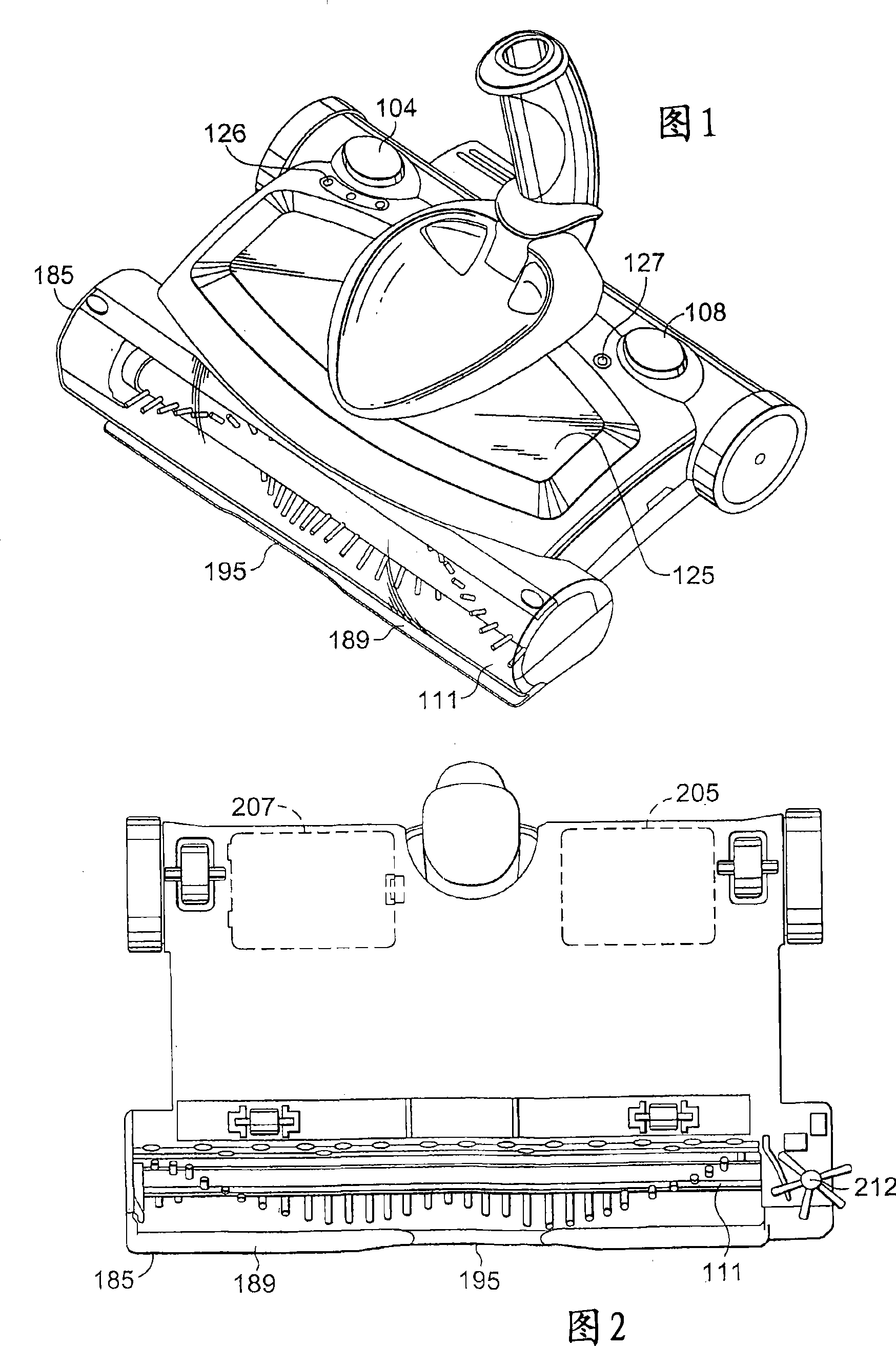
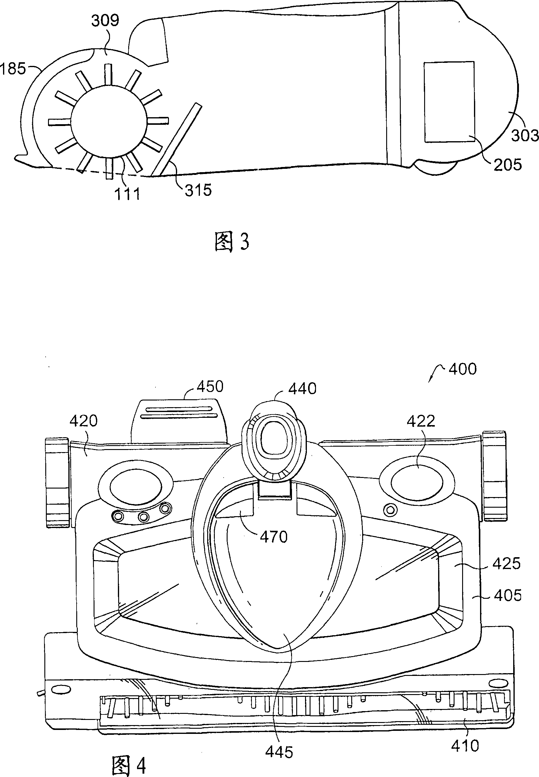
[0015] Various embodiments of the present invention may find application in surface cleaning devices such as sweepers and / or vacuum cleaners. Examples of sweeper embodiments are shown in FIGS. 1 , 2 and 3 .

[0016] Figure 1 depicts an embodiment of a surface cleaning device. The embodiment of Figure 1 includes a body 100, preferably molded from one or more plastic bodies. The body 100 may include two or more separate compartments, such as first and second compa...


PUM


Abstract

A surface cleaning device having a removable compartment (125, 425) for minimizing user manual action when emptying a dust cover in the removable compartment (125, 425). The above-mentioned removable partition (125, 425) is detachably fixed in the surface cleaning device. The removable spacer (125, 425) can be removed by actuating the first trigger mechanism (450). The dust cover can be emptied by a second trigger mechanism (470).

Description

Background technique [0001] Cleaning appliances such as sweepers provide the traditional tools for household cleaning. During operation, the dirt, dust and debris that the cleaning machine removes from the surface is collected in a container such as a dust cover. Over time, the dust cover will fill up and need to be emptied. Conventional methods generally require the user of the cleaning machine to manually operate the dust cover in order to empty the dust and debris. This manual operation of the dust cover can result in a large amount of debris coming into contact with the user's hands. Contents of the invention [0002] In one embodiment, a surface cleaning device is provided that includes a rotating brush disposed within a front compartment. The provided motor is used to drive the rotating brush. The surface cleaning device also includes an intermediate space formed by a dust collecting cover and a dust removal door, and the intermediate space is detachably fixed in t...

Claims


Application Information

Patent Timeline
Patent Type & Authority Applications(China)
IPC IPC(8): A47L11/33A47L5/30A47L5/26A47L11/40
CPCA47L5/26A47L11/4075A47L11/4041A47L11/4013A47L11/33A47L11/4025
Inventor C·里斯M·罗森兹韦格
Owner 欧洲普罗运营有限责任公司
Why Eureka
Try Eureka