Method for precisely getting pixel geometric location mapping relation between projector image and computer frame buffer image

A corresponding relationship, projector technology, applied in the fields of image processing and recognition, virtual reality, computer vision, can solve the problem of infeasible checkerboard corner recognition technology

Inactive Publication Date: 2008-05-28
WISESOFT CO LTD
View PDF0 Cites 18 Cited by
  • Summary
  • Abstract
  • Description
  • Claims
  • Application Information

AI Technical Summary

Problems solved by technology

Experiments show that simple checkerboard co

Method used


Image

  • Method for precisely getting pixel geometric location mapping relation between projector image and computer frame buffer image

Examples


Embodiment Construction

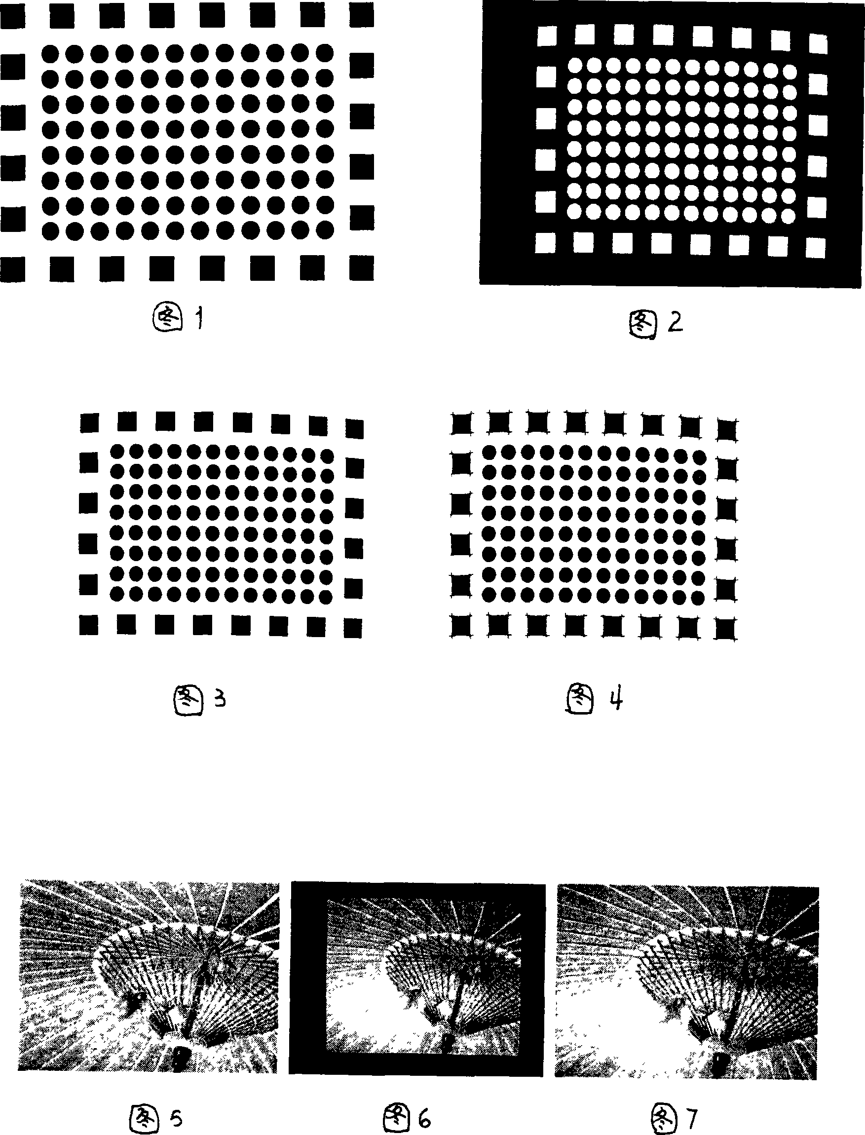
[0036]A method for accurately obtaining the pixel geometric position correspondence between a projector projected image and a computer frame buffer image, detailed pattern design: (1) description of characteristic pattern: the graphics distributed around the characteristic pattern are rectangles, and the middle graphics can be everything about Graphics distributed centrally, such as rectangles, circles, ellipses, etc. The distribution of all graphics in the geometric position is uniform distribution with respect to the feature points, and the graphics cannot be glued together visually, and can't be glued in the images taken by the camera. The characteristic points of the surrounding rectangle in the characteristic pattern are the four corner points, and the characteristic points of the inner figure are the center. The commonly used physical formula for calculating the center of mass of an object can be used for calculation; the number of graphics in the characteristic pattern ...


PUM


Abstract

The invention relates to a method correctly obtaining the corresponding relationship of the pixel geometric position between the projection image of a projector and the frame buffering image of a computer. The method includes the steps that: (1) a characteristic pattern of the projection image is determined, the circumference of the characteristic pattern is provided with a rectangle, and the center of the characteristic pattern is provided with a central symmetrical pattern that is uniformly arranged corresponding to a characteristic point; the parameter of the pattern is calculated; the characteristic pattern is projected on a displaying wall by a projector in an opposite color; the image of the characteristic pattern that is displayed on the displaying wall is shot with a digital camera; the shot image is segmented; every corner point of the rectangle surrounding the characteristic pattern is identified in the segmented image; every internal central symmetrical pattern is identified in the segmented image, and the center of the internal central symmetrical pattern of the characteristic pattern is calculated with the traditional statistical method; the two characteristic points are formed into a data matrix; the calculus of interpolation is carried out for the data matrix, thereby the matrix data after the interpolation establishes a corresponding geometric relationship with the original characteristic pattern on the pixel position.

Description

technical field [0001] The invention belongs to the fields of virtual reality, image processing and recognition, computer vision and the like. Background technique [0002] Multi-projection display wall technology is gaining attention as the demand for super-large screens and high-resolution displays continues to rise in areas such as business, entertainment and scientific research. In particular, using a projector to perform projection imaging in an imaging environment with a 360-degree cylindrical display wall and a dome can give people an immersive and realistic feeling, and has become a research hotspot in virtual reality imaging environment technology. [0003] However, due to the projection image deformation caused by factors such as projector lens, camera lens, and curved surface projection, it is the superposition of many nonlinear maps. It is difficult to build a model in a linear or piecewise linear manner, which does not always satisfy the current geometric correc...

Claims


Application Information

Patent Timeline
IPC IPC(8): G06T7/00
Inventor 王邦平张军
Owner WISESOFT CO LTD
Why Eureka
Try Eureka