
Shaping device for optical glass preform

A technology for optical glass and preforms, which can be used in glass forming, glass pressing, glass manufacturing equipment, etc., and can solve problems such as damage

Inactive Publication Date: 2008-06-04
ASIA OPTICAL CO INC
View PDF1 Cites 3 Cited by
  • Summary
  • Abstract
  • Description
  • Claims
  • Application Information

AI Technical Summary

Problems solved by technology

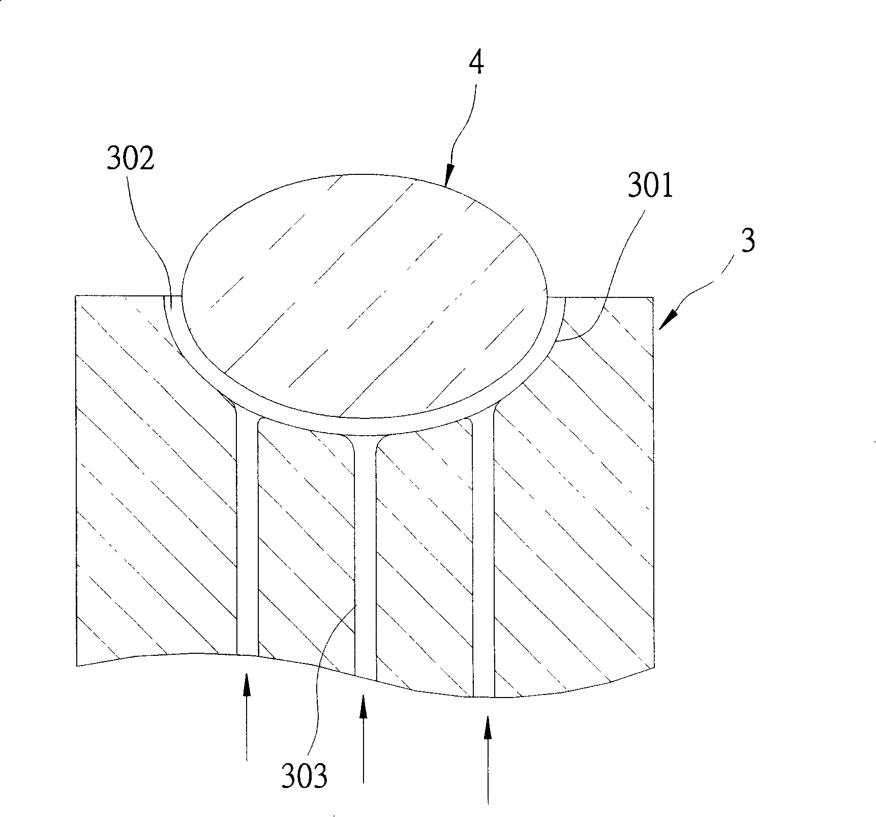
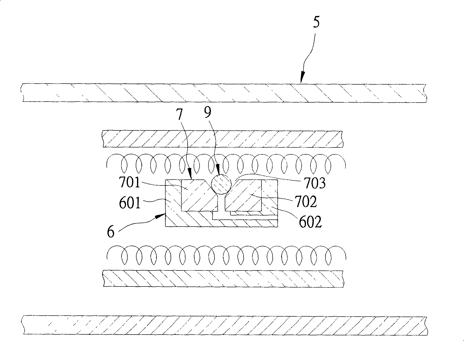
[0008] Although the forming method can directly form the molten glass into a glass lens through the above-mentioned device, yet, when this forming device transfers the glass preform 9, the glass preform 9 will also drop quickly due to gravity. to the lower mold core 801, therefore, the glass preform 9 will also have the problem of damage caused by hitting the lower mold core 801

Method used


Image

  • Shaping device for optical glass preform
  • Shaping device for optical glass preform
  • Shaping device for optical glass preform

Examples


Embodiment Construction

[0023] Before presenting a detailed description, it is noted that in the following description, similar components are denoted by the same numerals.

[0024] Referring to Fig. 5, 6, 7, a first preferred embodiment of the optical glass preform forming device of the present invention can be connected with a gas supply pipe 100 of an air pressure source (not shown), so that one from a platinum A molten glass 210 dripped from the outlet pipe 200 is formed into a spherical glass preform 220 with an outer diameter D. The forming device includes: a mold base 10 and a carrier 20 .

[0025] The mold base 10 has an upper mold body 11, a lower mold body 12 opposite to the upper mold body 11, an operating hole surface 13 around an axial direction X, and an operating hole defined by the operating hole surface 13. 14, and an air supply space 15 that surrounds the axial direction X and can communicate with the working hole 14 and the air supply pipe 100 of the air pressure source.

[0026] ...


PUM


Abstract

The invention relates to a forming device of optical glass preform, which can be connected with a pressure source, so as to form glass preform. The forming device comprises a die holder provided with an operation hole surface around an axial direction, an operation hole defined by the operation hole surface and an air supply space; the air supply space is communicated with the operation hole and pressure source along the axial direction; the air supply space is provided with an air vent part on the operation hole surface around the axial direction; the air vent part can output the air of the pressure source to the operation hole by the lateral side of the operation hole surface, thus enabling the glass preform to float over the air vent part.

Description

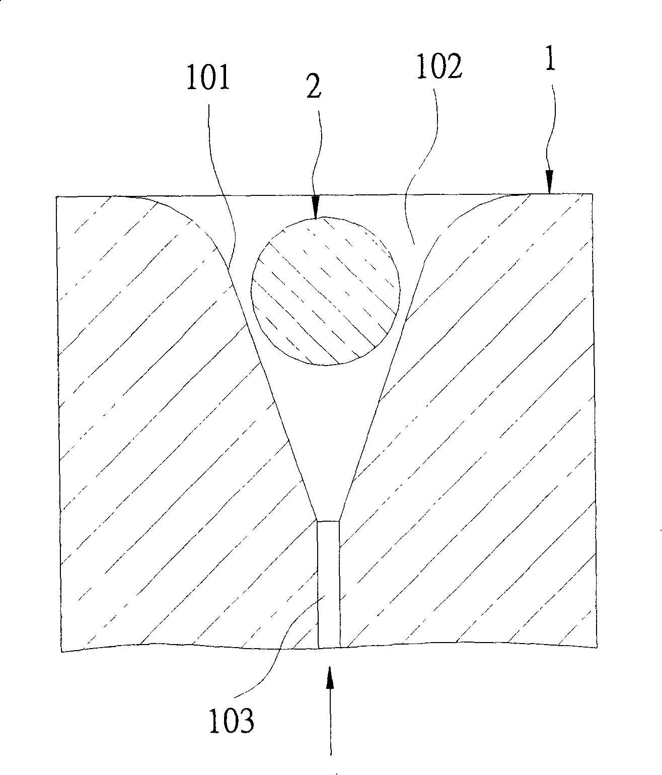
technical field [0001] The invention relates to a forming device, in particular to an optical glass preform forming device capable of preventing the impact damage of the glass preform during the forming process. Background technique [0002] Such as figure 1 As shown, there is an existing floating forming device for forming a glass preform 2, which includes a forming seat 1, which can be connected with an air pressure source (not shown) for supplying gas, and the forming seat 1 It has a forming surface 101 , a forming hole 102 with a V-shaped cross section, and an air inlet 103 communicating with the forming hole 102 and the air pressure source and having a diameter smaller than the outer diameter of the glass preform 2 . Thereby, when a platinum outflow tube (not shown) drops a molten glass (not shown) into the forming hole 102, the gas supplied by the air pressure source can be transported from the air inlet 103 to the forming hole 102. The hole 102 is formed so that the...

Claims


Application Information

Patent Timeline
IPC IPC(8): C03B11/08C03B40/04
CPCC03B40/04C03B11/08C03B7/12C03B2215/63
Inventor 王坤池高伯菘
Owner ASIA OPTICAL CO INC
Learn More