Mechanical key puzzle lock

A mechanical combination lock and key technology, used in combination locks, building locks, and numbered locks, etc., can solve the problems of being easily damaged by impact, cannot be reused, and keys are easy to lose.

Inactive Publication Date: 2008-06-04
田远林
View PDF1 Cites 6 Cited by
  • Summary
  • Abstract
  • Description
  • Claims
  • Application Information

AI Technical Summary

Problems solved by technology

[0002] At present, the existing mechanical key combination lock overcomes the shortcomings of the key carrying the key and being easy to lose, being copied, and the electronic lock requires electricity and cannot be used in harsh environments or is easily damaged by impact. The mechanical combination lock with the patent No. 89107364.7 is just The technical solution of this equipment is disclosed
However, there are unreasonable mechanical structures and single working performance in the existing combination locks, so that the number of password groups is small, and its sequence and arrangement are easy to be mastered by outsiders to crack the password, and the same key cannot be reused, so it is difficult to be used. Users who require a higher security level accept

Method used


Image

  • Mechanical key puzzle lock
  • Mechanical key puzzle lock
  • Mechanical key puzzle lock

Examples


specific Embodiment 1

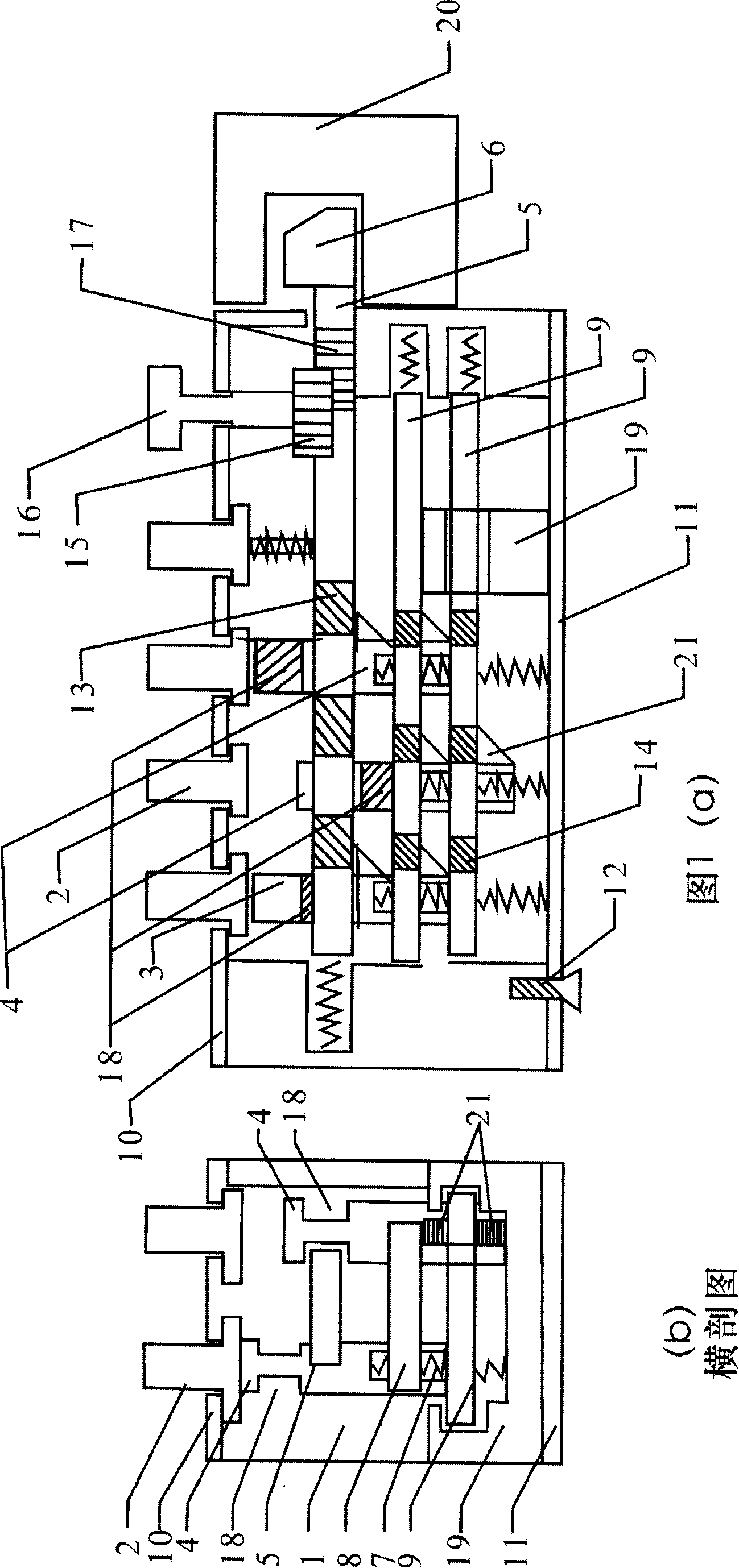
[0010] As shown in Fig. 1, the upper cover plate 10 is a rectangle with double rows of regular round holes, and the round holes are equal to the upper and lower connected vertical column hook guide grooves and opening knobs of the bracket, which are used to fix and guide the movement of the extended force arm of the button. , the upper cover plate 10 is fixed with the upper part of the bracket seat with screws, and the button 2 is composed of a cylindrical arm extending slightly longer than the stroke of the column hook on a column hook contact platform and a stable insertion rod extending downward, and the perimeter of the column hook contact platform is slightly larger than Extend the perimeter of the force arm, insert the stabilizing rod into the support seat after inserting the return spring, so as to ensure that the column hook is pressed down by the button and enters the predetermined hanging plate and loses support and rebounds to the initial working position. The locking...

specific Embodiment 2

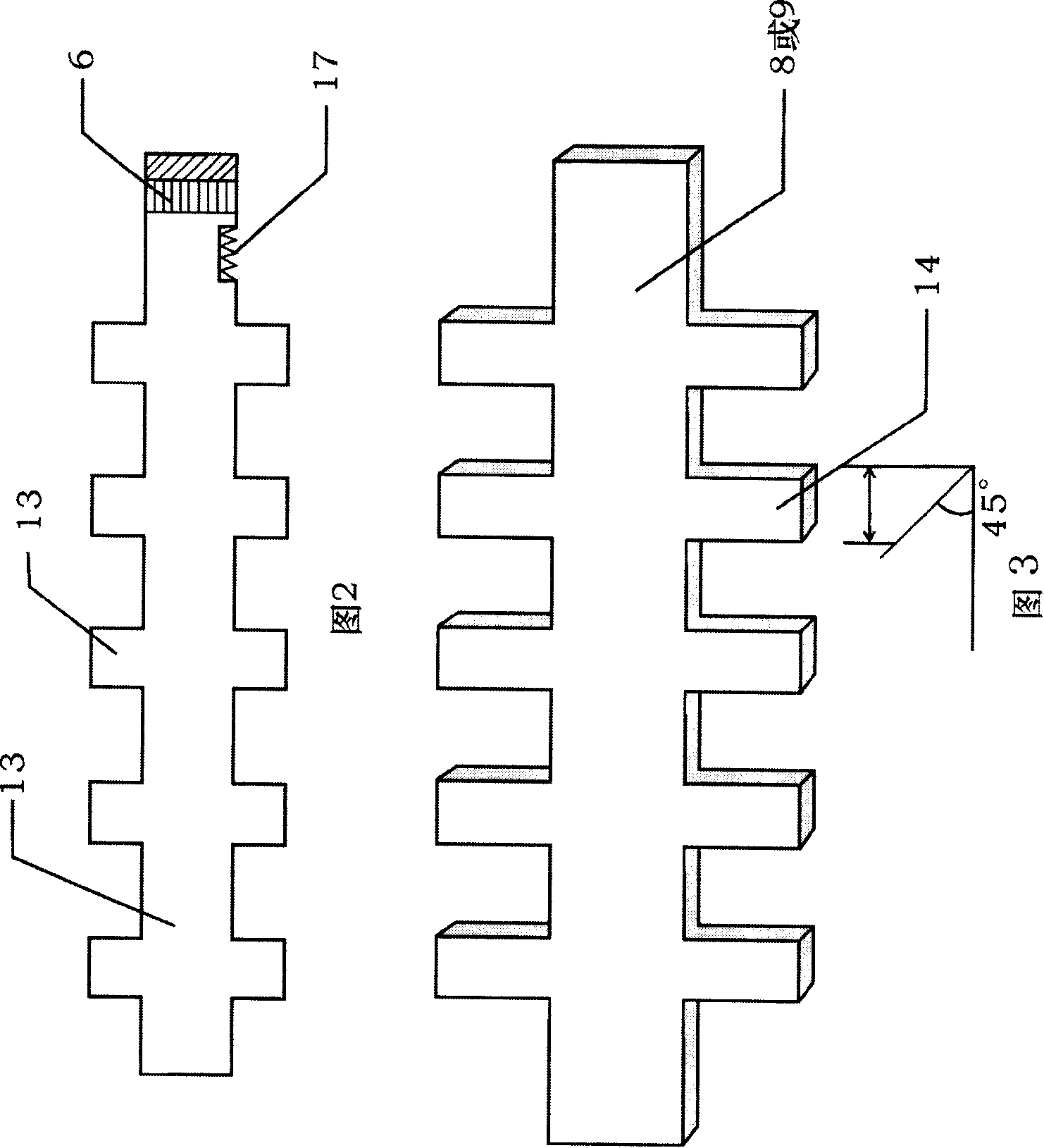
[0011] This embodiment adopts the input method of multi-tooth post hooks, which can be input in the order of large angles to small angles, and can also be carried out in the way that the front tooth angles are the same and the rear tooth angles are changed. However, in the multi-level or cross-layer column hook input mode , the tooth angle of its level and level can be freely selected, and the purpose is to make outsiders unable to detect the function of the post hook or which level to use, so that it cannot know the number and arrangement of the password.

[0012] According to the password number and password group quantity requirements, the post hook usage of various performances can be set according to requirements, and the hook plate of this example is made up of the first card hook plate 8 and the second card hook plate 9, and they all are one Vertically and horizontally cross rectangular support flat plate is formed, and its transverse support contacts with column hook an...


PUM


Abstract

The invention discloses a mechanical button coded lock which finishes locking and unlocking through an external button driving an internal connected column hook, comprising a support saddle (1), cipher buttons (2), an upper cover plate (10), a lower cover plate (11), a lock plunger (5), a bolt (6) and a lock catch (20), wherein, a knob (16) is opened, cipher column hooks (4) are arranged inside the support saddle (1), the cipher column hooks (4) are in one to one correspondence with the cipher buttons (2); two clamped and hung hook plates (8), (9) are arranged inside the support saddle (1); the cipher column hook (4) penetrates the two clamped hook plates (8), (9); the clamped hook plate (8) and the clamped hook plate (9) are parallel; the cipher buttons (2) totally have 11 buttons, including zero to nine and a 'full stop'. The invention has the advantages of multilayer clamping and hanging, multiple group ciphers, reusing availability of the same button, concealed inputted buttons, etc. The invention is further improved in the aspects of cipher group quantity and security.

Description

technical field [0001] The invention relates to a mechanical lock, in particular to a mechanical key coded lock which is locked and unlocked by driving an inline column hook through an external key. Background technique [0002] At present, the existing mechanical key combination lock overcomes the shortcomings of the key carrying the key and being easy to lose, being copied, and the electronic lock requires electricity and cannot be used in harsh environments or is easily damaged by impact. The mechanical combination lock with the patent No. 89107364.7 is just This equipment technical scheme is disclosed. However, there are unreasonable mechanical structures and single working performance in the existing combination locks, so that the number of password groups is small, and its sequence and arrangement are easy to be mastered by outsiders to crack the password, and the same key cannot be reused, so it is difficult to be used. Accepted by users who require a higher security...

Claims


Application Information

Patent Timeline
Patent Type & Authority Applications(China)
IPC IPC(8): E05B37/20
Inventor 田远林
Owner 田远林
Why Eureka
Try Eureka