Electronic apparatus

A technology of electronic devices and electronic components, applied in the direction of circuits, electrical components, electric solid devices, etc., can solve problems such as inability to cool

Inactive Publication Date: 2008-06-04
KK TOSHIBA
View PDF1 Cites 0 Cited by
  • Summary
  • Abstract
  • Description
  • Claims
  • Application Information

AI Technical Summary

Problems solved by technology

As a result, in the case where the heat-generating position is changed due to a change in the function mode, or in the case where the temperature inside the device is increased due to the additional installation of an optional unit, there arises a problem that proper cooling cannot be performed.

Method used


Image

  • Electronic apparatus
  • Electronic apparatus
  • Electronic apparatus

Examples


Embodiment Construction

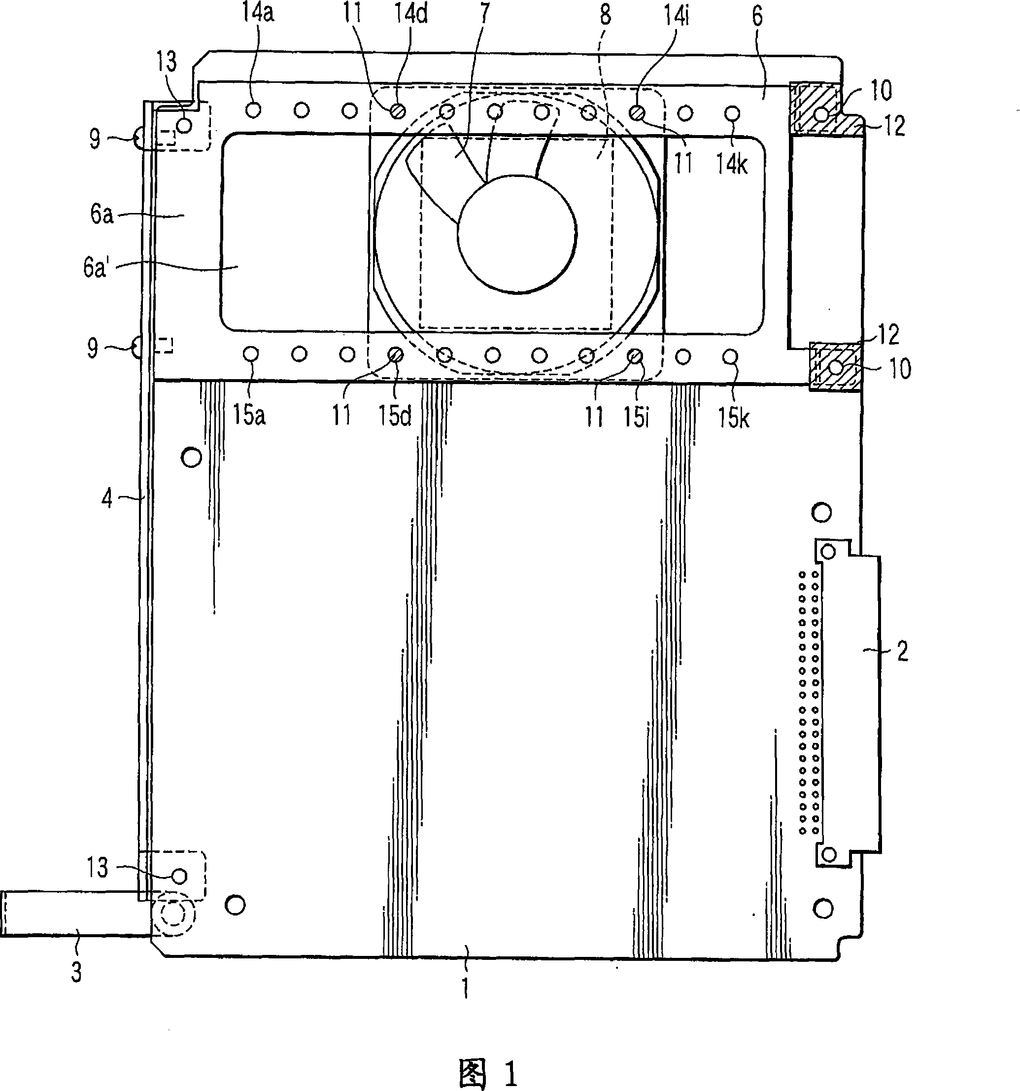
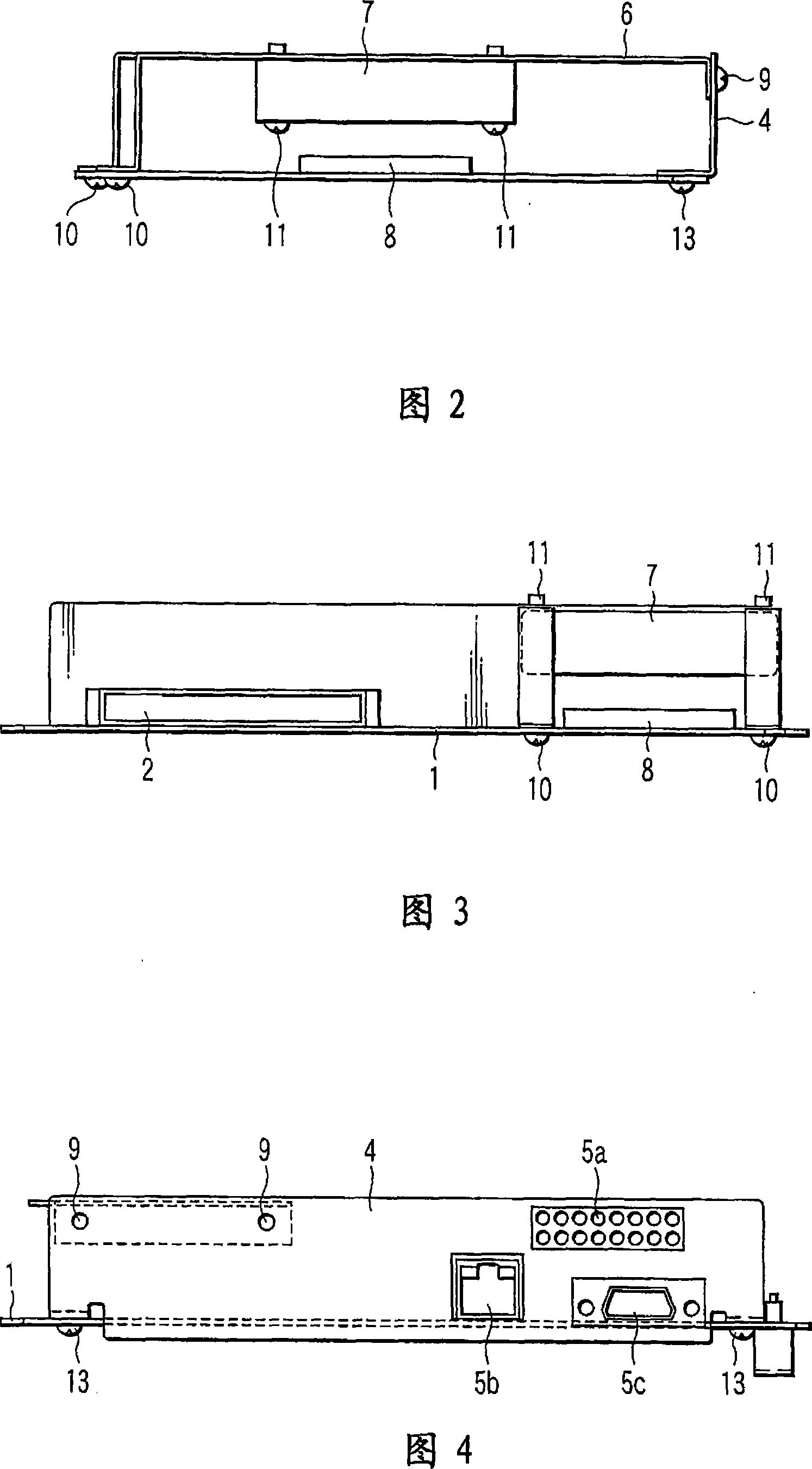
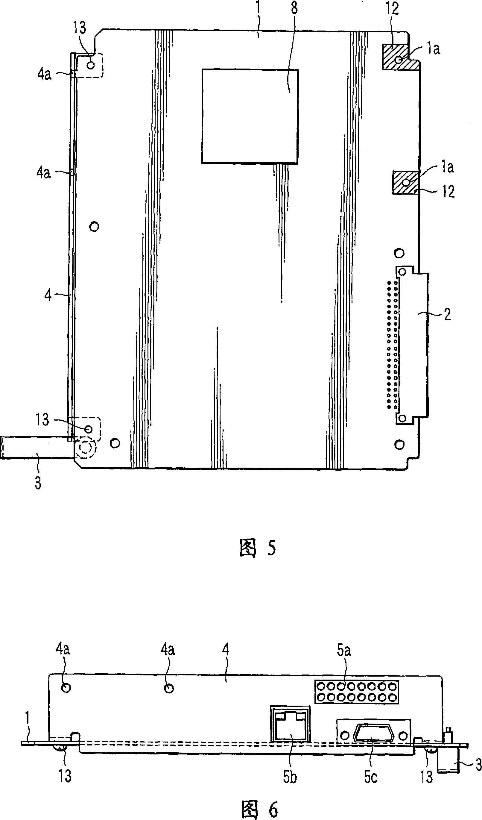
[0031] Various embodiments according to the present invention are hereinafter described with reference to the accompanying drawings. Generally speaking, according to an embodiment of the present invention, an electronic device includes: a circuit board; an electronic component that is disposed on the circuit board and generates heat; a mounting part that is disposed on the circuit board and There are a plurality of installation areas; and a fan unit is installed to at least one installation area selected from the plurality of installation areas of the installation portion and cools the electronic component.

[0032] FIG. 1 is a plan view showing an electronic circuit unit of an electronic device such as a portable computer according to an embodiment of the present invention. FIG. 2 is a front view of the electronic circuit unit, FIG. 3 is a side view of the electronic circuit unit, and FIG. 4 is another side view of the electronic circuit unit.

[0033] The electronic circuit...


PUM


Abstract

An electronic apparatus includes a circuit board (1), an MPU (8) which is provided on the circuit board (1) and produces heat, an attachment stay (6) which is provided on the circuit board (1) and has a plurality of attachment areas, and a fan unit (7) which is attached to at least one selected from the plurality of attachment areas of the attachment device (6), and cools the MPU (8).

Description

technical field [0001] An embodiment of the present invention relates to an electronic device in which a fan unit for cooling electronic components is installed. Background technique [0002] Generally, in an electronic device such as a personal computer, an IC, an LSI, an MPU, and the like are disposed on a circuit board (hereinafter, these components are representatively referred to as "MPU"). In order to process various multimedia information such as characters, sounds, and images, the processing speed and functions of the MPU have been continuously enhanced. [0003] Meanwhile, in the MPU, as integration density develops and functions increase, power consumption also increases, and heat generated during operation also tends to increase accordingly. [0004] In order to improve the heat radiation of the MPU, a motor-driven fan unit is provided inside the device (see Japanese Patent Application Laid-Open Publication No. 2000-13070). [0005] However, in the related art, ...

Claims


Application Information

Patent Timeline
Patent Type & Authority Applications(China)
IPC IPC(8): H05K7/20G06F1/20H01L23/40
CPCH05K7/20172
Inventor 横沟猛
Owner KK TOSHIBA
Why Eureka
Try Eureka