Blender arm and food processor

A technology of food processing and agitator, applied in mixers with rotating agitating devices, chemical instruments and methods, transportation and packaging, etc., can solve problems such as danger, achieve rapid cleaning, and reduce the risk of injury

Inactive Publication Date: 2008-06-04
KONINKLIJKE PHILIPS ELECTRONICS NV
View PDF1 Cites 19 Cited by
  • Summary
  • Abstract
  • Description
  • Claims
  • Application Information

AI Technical Summary

Problems solved by technology

[0004] The cutter equipment described in EP 1 407 701 A1 has the disadvantage of having to touch the knife when disassembling and reassembling the equipment
This can be quite dangerous where the knife is a blade or a knife

Method used


Image

  • Blender arm and food processor
  • Blender arm and food processor
  • Blender arm and food processor

Examples


Embodiment Construction

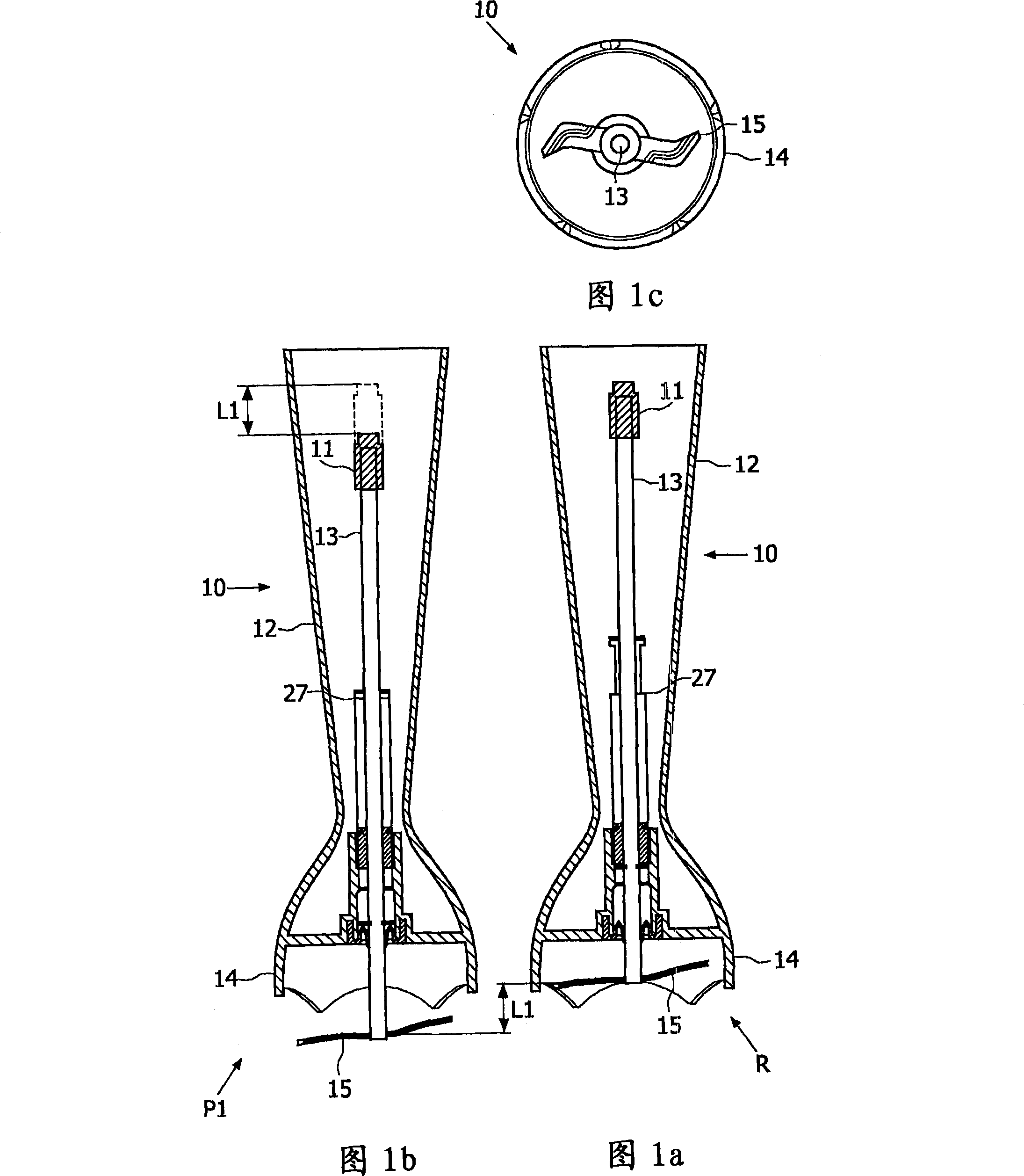
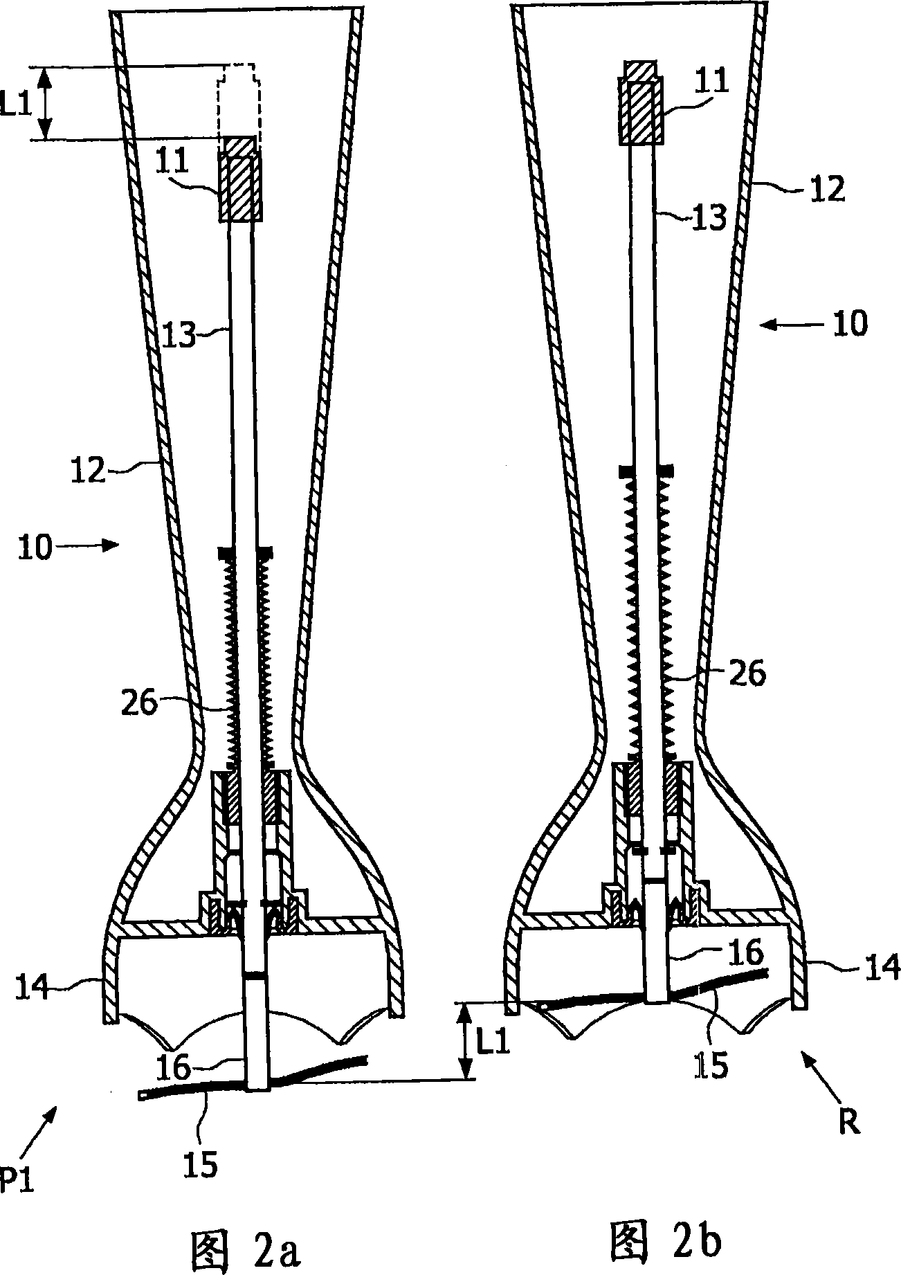
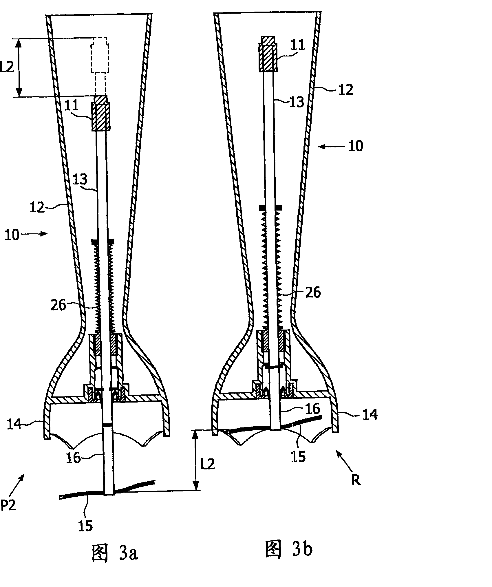
[0033] Fig. 1a, Fig. 1b, Fig. 1c show the first embodiment of the stirrer equipment 10 according to the present invention, Fig. 1a and Fig. 1b are the axial section, Fig. 1c is the bottom section. The main part is the tubular body 12 including the axis of rotation 13 . The lower end of the tubular body 12 (as shown in FIG. 1 ) is enlarged to form a cover 14 as a peripheral protection portion around the blade 15 fixed on the lower end of the rotating shaft 13 . The upper end of the rotary shaft 13 shows a connector 11 for connecting the rotary shaft 13 to a power supply unit (not shown) to cause the rotary shaft to rotate and thereby run the blade 15 . The rotating blade 15 then chops, purees, or mixes its surroundings.

[0034] Retained within the tubular body 12 is a rotating shaft 13 which can be moved axially by pushing the connector 11 with, for example, a finger, thereby bringing the blade 15 from a retracted position R ( FIG. 1 a ) inside the housing 14 to outside the h...


PUM


Abstract

A blender arm includes a tubular body equipped at one end with a connection for a power unit. The blender arm further includes a rotary shaft having a tool at the end opposite to the connection end. A peripheral protection is provided around the tool. The rotary shaft with the tool is attached movably in axial direction to the tubular body so that the tool may be positioned in a retracted position for operation or a protracted position for cleaning, without having to touch the tool with the hands. The blender arm may further include a resilient element, functionally connected to the tubular body and the rotary shaft, for moving the rotary shaft between the protracted and retracted positions. When the rotary shaft is releases, the tool automatically returns to the retracted position.

Description

technical field [0001] The present invention relates to a blender arm having a tubular body provided at one end with a connector for a power supply unit at one end and a food processor equipped with such a blender arm, the blender arm being axially A rotary shaft is included with a cutter at the opposite end from the connector end, the cutter being provided with a peripheral guard around the cutter. Background technique [0002] Food processors equipped with a blender are commonly used for chopping, pureeing, grinding, chopping or blending, for example when making soups, sauces, beverages and the like. During processing, sometimes some residues such as dietary fibers are adsorbed in the area behind the stirring knife. A common method for cleaning agitator equipment is to rinse the end with the cutter and peripheral guard under running water. This is usually not enough to completely remove the residue. Complete cleaning is difficult because there is no direct access to the...

Claims


Application Information

Patent Timeline
Patent Type & Authority Applications(China)
IPC IPC(8): A47J43/07B01F27/71
CPCA47J2043/04427Y10S366/601A47J43/0755A47J43/0705
Inventor J·M·拉迈罗·维拉里诺H·奥伯斯泰纳
Owner KONINKLIJKE PHILIPS ELECTRONICS NV
Why Eureka
Try Eureka