Circuit board fixing mechanism

A fixing mechanism and circuit board technology, applied in the direction of circuit arrangement, elastic/clamping device, etc. on the support structure, can solve the problems of inconvenience, complex installation structure, reduced efficiency, etc., to overcome the inconvenience of stacking, reduce the use of parts, save The effect of parts cost

Inactive Publication Date: 2008-06-11
INVENTEC CORP
View PDF0 Cites 16 Cited by
  • Summary
  • Abstract
  • Description
  • Claims
  • Application Information

AI Technical Summary

Problems solved by technology

However, a handle seat 130 and a handle 140 need to be arranged on the motherboard 100, which is extremely inconvenient for the stacking and storage of the motherboard, and non-standard motherboard production and assembly equipment needs to be added, and the handle 140 is easy to fall off, so The existing structure is still inconvenient
[0006] The above existing technology can save installation tools when used for motherboard installation, and can be installed quickly. However, the existing technology not only increases the manufacturing cost, but also inconvenient storage and material preparation, and the efficiency is also reduced. Moreover, when expanding to multi-chip motherboards There is also the problem of complex installation structure in the implementation of the circuit board, so it is necessary to develop a circuit board fixing mechanism with a simple structure and low cost technology

Method used


Image

  • Circuit board fixing mechanism
  • Circuit board fixing mechanism
  • Circuit board fixing mechanism

Examples


no. 1 example

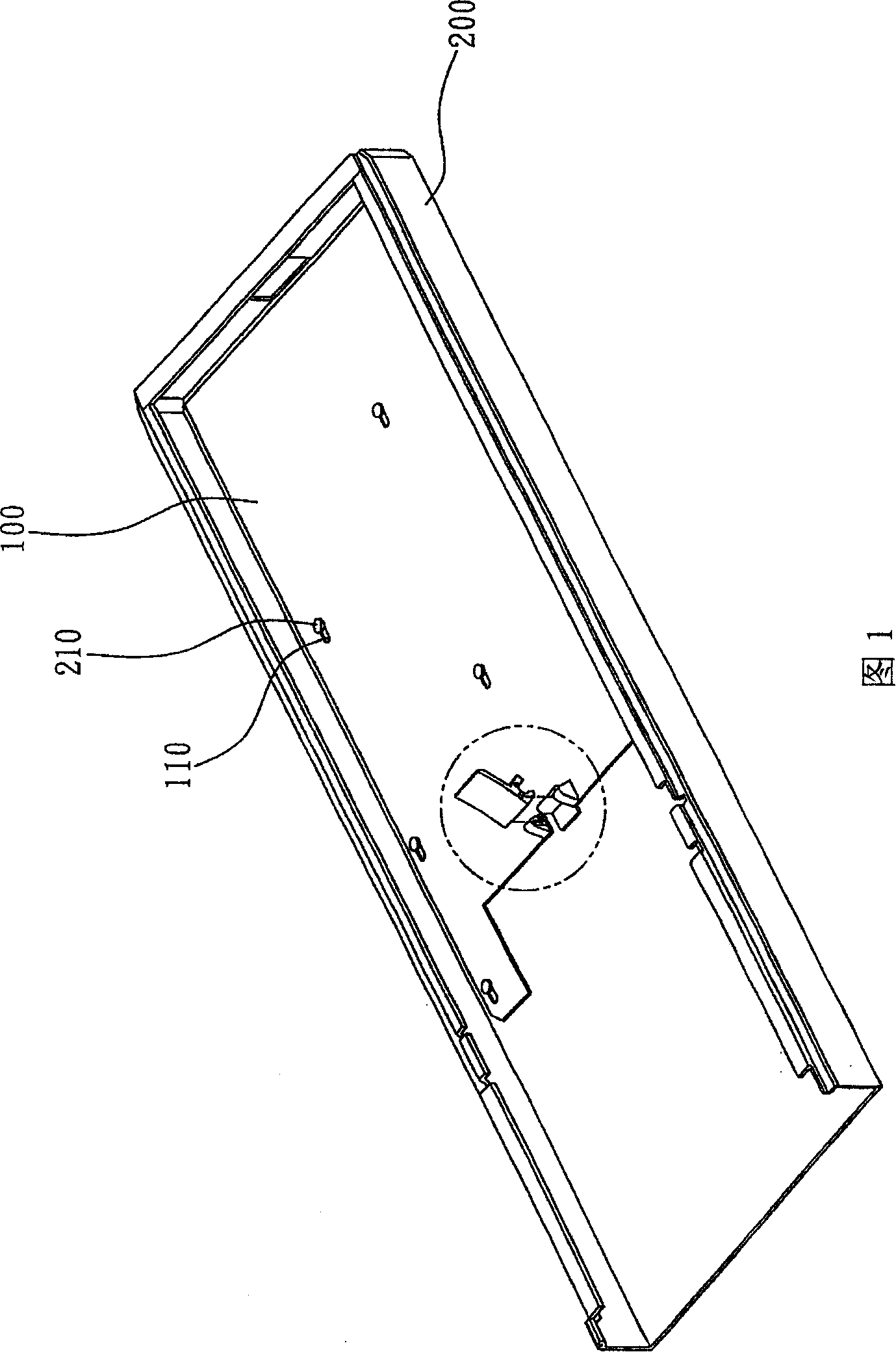
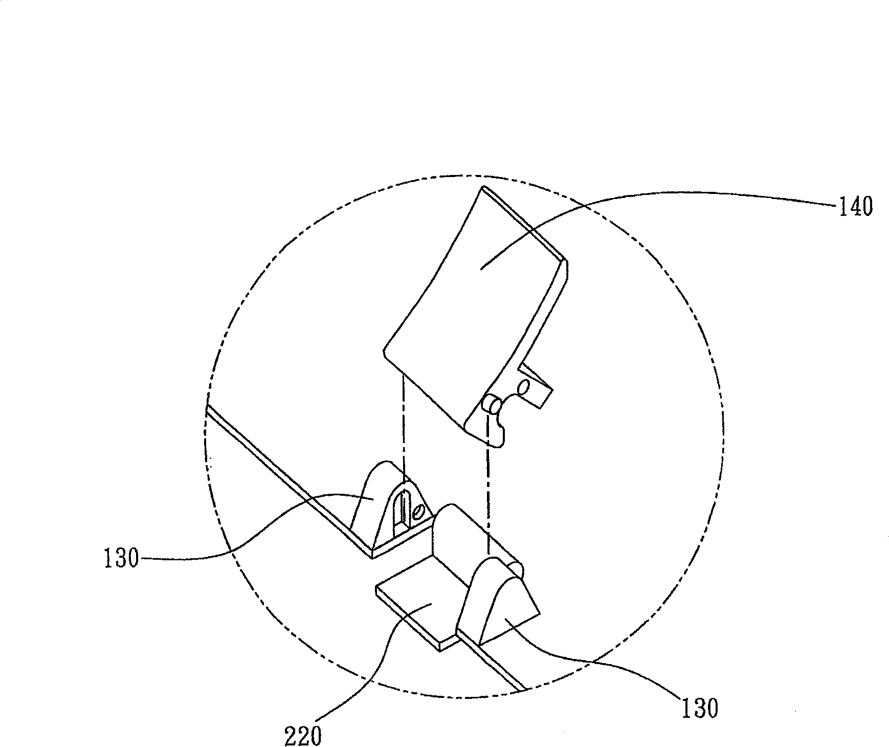
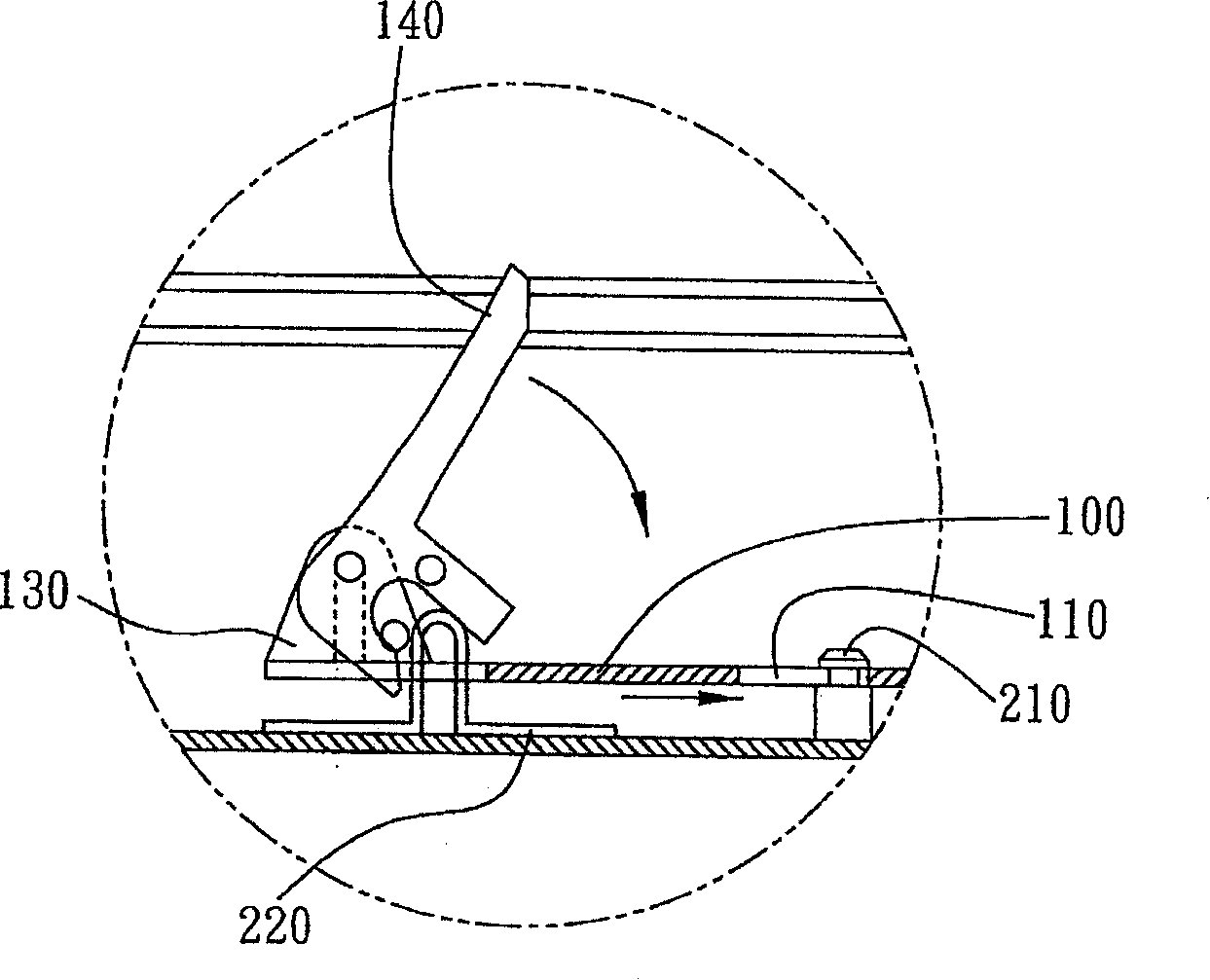
[0042] Such as image 3 The circuit board fixing mechanism shown is used to fix a circuit board 4 with a plurality of openings 41 on a setting surface 3. The circuit board 4 is an example of a mainboard used in a server, and the setting Surface 3 takes the chassis bottom plate of the server as an example. In addition, the same side of each of the openings 41 is provided with a reduced engaging section 411, that is, the opening 41 with the engaging section 411 is equivalent to a gourd as a whole. hole. The circuit board fixing mechanism of the present invention includes a first positioning portion 43 disposed on the circuit board 4 , a plurality of supports 31 disposed on the setting surface 3 , and an elastic body disposed on the setting surface 3 and having a second positioning portion 331 . The member 33, through the corresponding engagement of each support member 31 with the engaging section 411, can provide two-direction degree of freedom restriction, and at the same time...

no. 2 example

[0050] Image 6 According to the drawings drawn according to the second embodiment of the circuit board fixing mechanism of the present invention, the same elements as those of the first embodiment are represented by the same or similar element symbols, and detailed descriptions are omitted so as to make the description of this case Clearer and easier to understand.

[0051] The biggest difference between the second embodiment and the first embodiment is that the elastic member 33 of the first embodiment is an elastic arm with a bump on the top as an example, while the second embodiment is a button with a keycap .

[0052] As shown in the figure, the circuit board fixing mechanism shown in this embodiment also includes a first positioning portion 43 provided on the circuit board 4, a plurality of support members 31 provided on the installation surface 3, and a plurality of support members 31 arranged on the installation surface. 3 and the elastic member 33' with the second p...


PUM


Abstract

A circuit board fixing mechanism is used to fix a circuit board with a plurality of openings on a setting surface with each opening provided with a contracting clamping section at the same side, wherein the fixing mechanism at least comprises a first locating part arranged on the circuit board, a plurality of support pieces provided with necks and arranged on the setting surface and an elastic piece provided with a second locating part and arranged on the setting surface; through the corresponding clamping between the necks of the support pieces and the clamping sections, freedom degree limitation in two directions can be provided; meanwhile, by means of the elastic locating of the second locating part of the elastic piece on the first locating part, freedom degree limitation in a third direction can be provided.

Description

technical field [0001] The invention relates to a circuit board fixing mechanism, in particular to a tool-free circuit board fixing mechanism. Background technique [0002] As for the fixing technology of the circuit board, the common method is to lock the screw, but when considering the convenience of assembly or disassembly, the method of snapping or buckling is mostly used. Taking the mainboard fixing technology applied in the server as an example, the traditional method is to preset a number of support columns with screw holes on the installation surface of the server chassis, and form a coplanar plane with each support column to support the mainboard, and then use The screws correspond to each support column to be locked one by one. This method can use the support column to raise the main board to provide electrical isolation from the chassis, and increase the air flow space at the bottom of the main board to improve the heat convection effect, but the alignment and us...

Claims


Application Information

Patent Timeline
Patent Type & Authority Applications(China)
IPC IPC(8): H05K7/12
Inventor 李景新郑再魁
Owner INVENTEC CORP
Why Eureka
Try Eureka