
Pneumatic conveying device of tyre forming machine and method thereof

A tire building machine and pneumatic conveying technology, which is applied to pneumatic conveying devices and pushes the air film field of materials. The effect of low power and supporting cost

Active Publication Date: 2013-03-06
MESNAC
View PDF0 Cites 0 Cited by
  • Summary
  • Abstract
  • Description
  • Claims
  • Application Information

AI Technical Summary

Problems solved by technology

At present, the conveying of the above-mentioned materials is generally carried out by a conveyor belt driven by a motor. Although the materials are not stretched, a corresponding conveying power device with a transmission mechanism needs to be added, and the structure is relatively complicated and takes up a large amount of installation and use. space, and is not suitable for long-distance transportation
[0004] Another existing conveying method is to use a two-way bearing or a conveying device with template embedded universal balls. During the conveying process, there is relative slippage between the template and the material, and the frictional resistance is relatively large. Long-distance conveying is easy to cause damage to the material stretching

Method used


Image

  • Pneumatic conveying device of tyre forming machine and method thereof
  • Pneumatic conveying device of tyre forming machine and method thereof
  • Pneumatic conveying device of tyre forming machine and method thereof

Examples


Embodiment 1

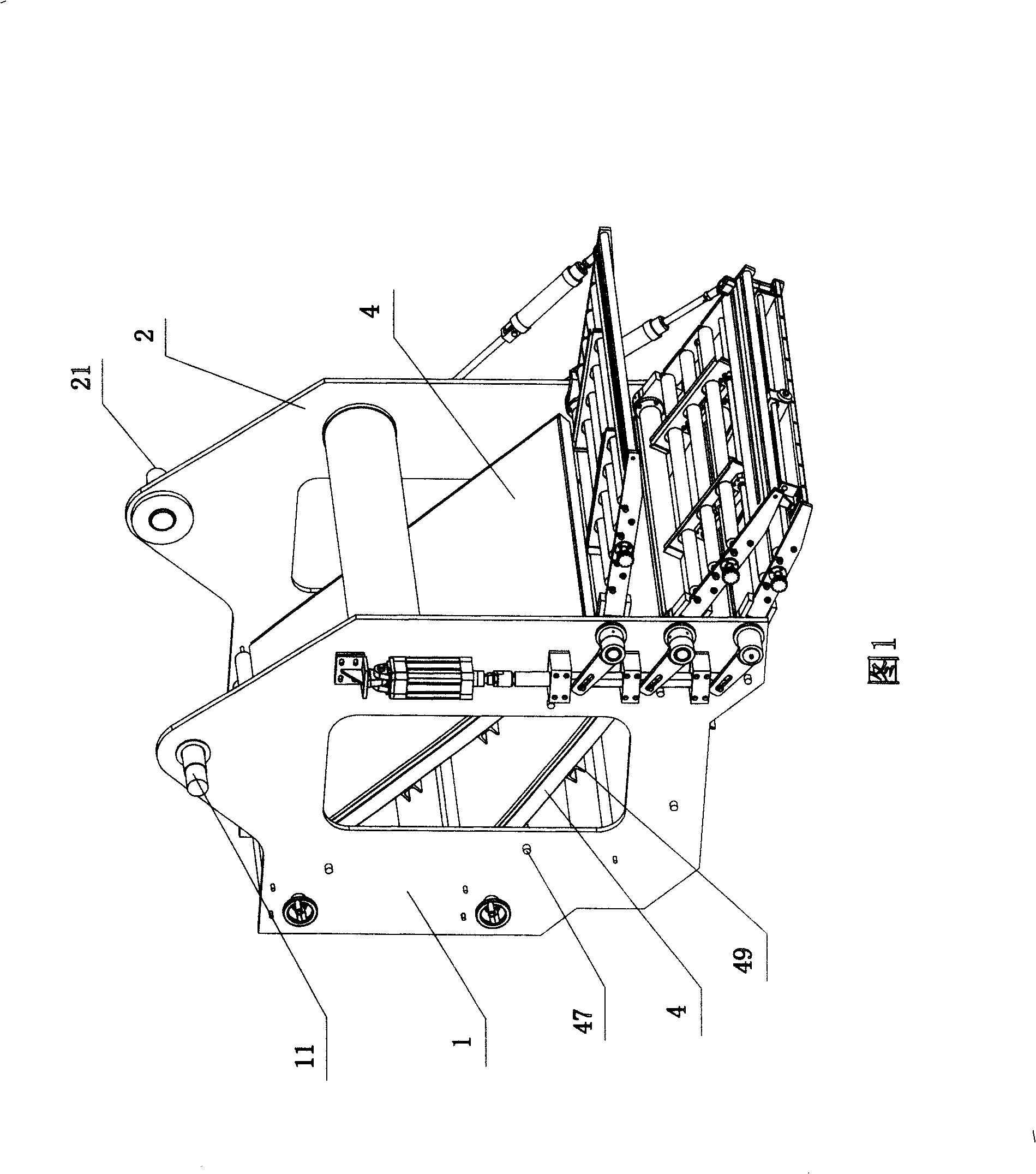
[0038] Example 1, such as Figure 1 to Figure 5 As shown, in the tire building machine using the pneumatic conveying device, the frame is respectively connected to the left wall panel 1 and the right wall panel 2 through the fixed hinge 11 and the fixed hinge 21 .

[0039] Between the left wallboard 1 and the right wallboard 2, two sets of centering devices 3 and three layers of conveying templates 4 connected in sequence are fixed. Wherein, the fixed shaft 47 fixed between the left wallboard 1 and the right wallboard 2 is installed under the conveying formwork 4, the fixing seat 48 is buckled on the fixed shaft 47, and the reinforcing rib arranged transversely is fixed below the conveying formwork 4 tendons49.

[0040] Through the above structure, when changing laminating drums of different specifications, the overall adjustment device of the frame can push and drive the left wall panel 1 and the right wall panel 2, and then drive the pneumatic conveying device as a whole to...


PUM


Abstract

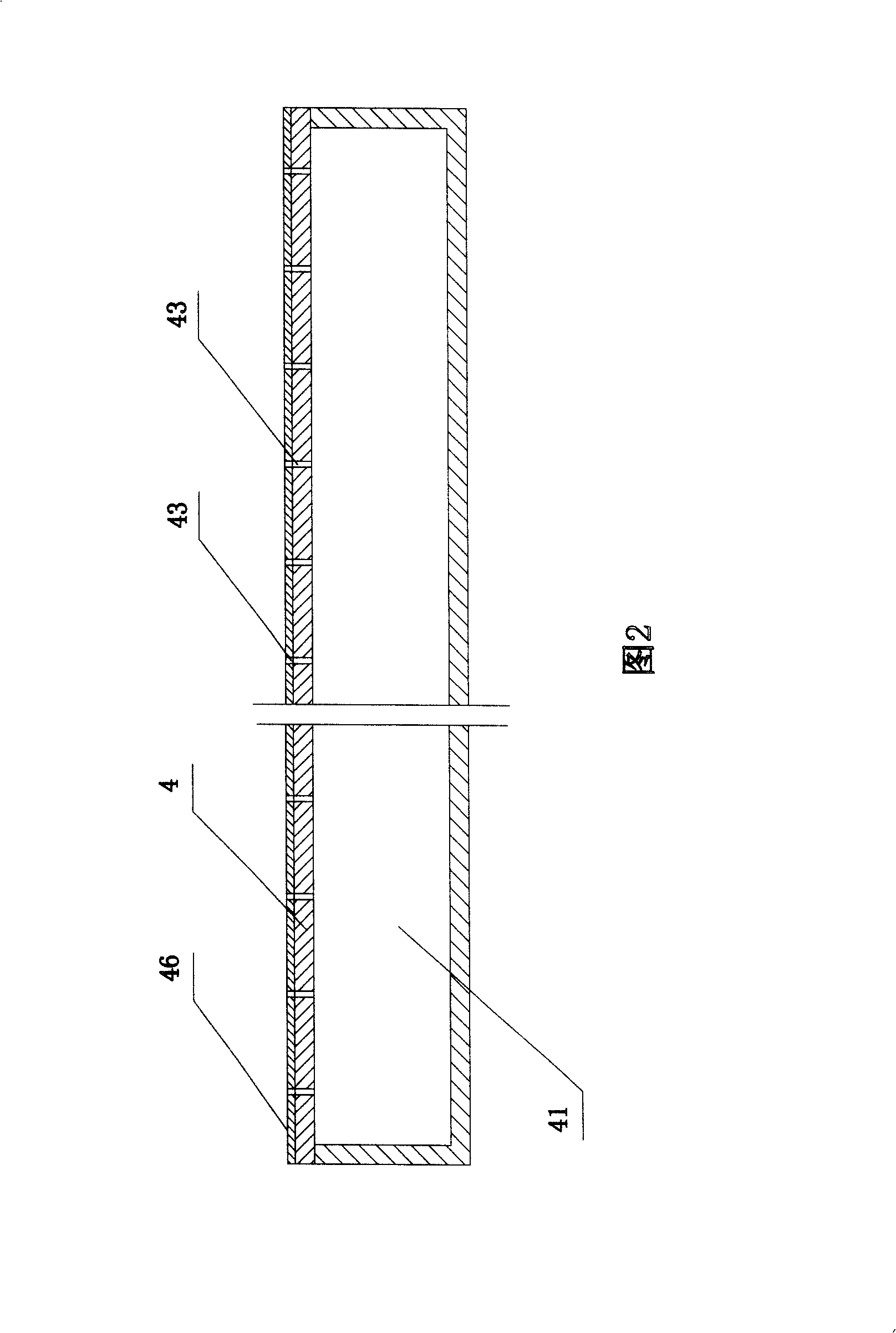
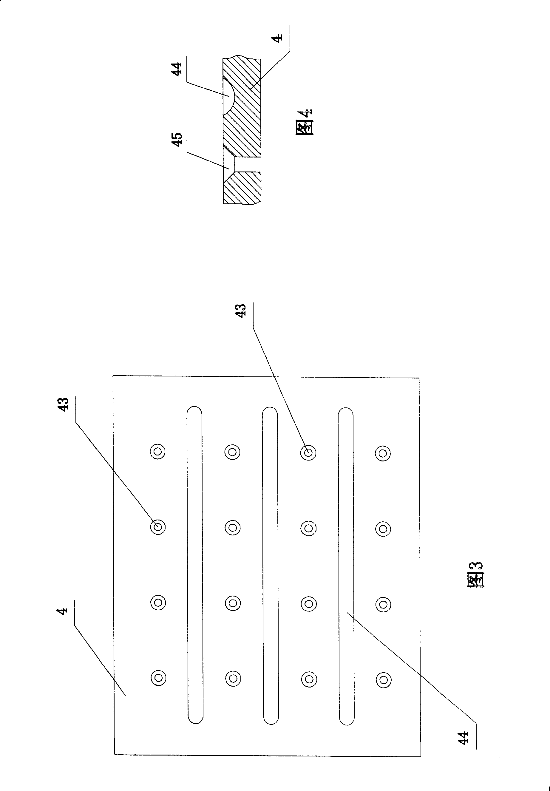
The invention provides a pneumatic conveying device of a tire building machine and a method of the device. A hollow chamber is arranged in a conveying template; compressed air in an external air source is introduced into the chamber from an air inlet hole at the bottom of the chamber; the compressed air is discharged into the surface of the conveying template through air outlet holes on the top of the chamber, so that an air mould is formed between the conveying template and conveyed material to realize the method that the material is conveyed forward pushed by the air mould. The material is suspended above the conveying template through the discharge of the compressed air, so that the friction force between the material and the conveying template is reduced, and the material is avoided to be stretched, which is suitable for long distance conveying. The conveying template at least has one layer with a hollow inner chamber. The bottom of the chamber is provided with an air inlet hole which is connected with the external air source and can introduce the compressed air into the chamber; the top of the chamber is provided with a plurality of air outlet holes which can discharge the air in the chamber into the surface of the conveying template.

Description

technical field [0001] The invention relates to a pneumatic conveying device applied to a tire building machine and a method thereof, in particular guiding compressed air to the surface of a conveying template to form an air film for pushing materials, belonging to the field of rubber processing machinery. Background technique [0002] Tires are the main action components of motor vehicles. The quality of tire processing determines the stability of its performance. Whether it meets the requirements of processing standards will directly determine the safe use of motor vehicles. At present, in the rubber tire processing process, the lamination and pressing process of various parts of the semi-finished tire on the building drum is the key to the quality standard of the finished tire. [0003] The conveying and winding of cord, inner liner, belt and other materials are more important steps. At present, the conveying of the above-mentioned materials is generally carried out by a...

Claims


Application Information

Patent Timeline
Patent Type & Authority Patents(China)
IPC IPC(8): B29C31/00B29D30/06B65G51/03B65H20/00B65H5/22
Inventor 袁仲雪程继国曹大伟秦昌峰杨慧丽胡勐周敬铠
Owner MESNAC
Learn More