Electrical connector for flat conductor

An electrical connector, a flat type technology, applied in the field of electrical connectors for flat conductors, can solve problems such as different pressing forces, and achieve the effects of balanced pressing force, balanced and stable contact, and expanded pressing area

Active Publication Date: 2011-07-13
HIROSE ELECTRIC GROUP
View PDF1 Cites 0 Cited by
  • Summary
  • Abstract
  • Description
  • Claims
  • Application Information

AI Technical Summary

Problems solved by technology

That is, resulting in different pressing forces

Method used


Image

  • Electrical connector for flat conductor
  • Electrical connector for flat conductor
  • Electrical connector for flat conductor

Examples


Embodiment Construction

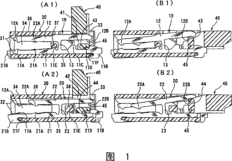
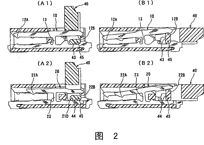
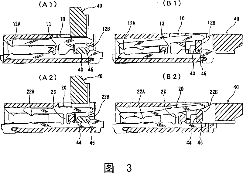
[0029] based on the following Figure 1 to Figure 3 Embodiments of the present invention will be described. figure 1 In the illustrated connector, multi-terminals formed by processing a metal plate and having a flat surface parallel to the paper are arranged at predetermined intervals along a direction perpendicular to the paper. The two terminals 10, 20 are alternately arranged, figure 1 (A1) shows a sectional view at the position of one terminal 10, figure 1 (A2) shows a cross-sectional view at the position of the other terminal 20 . figure 1 (A1) and figure 1 (A2) shows that the pressurizing member described later is in the open position, and figure 1 (B1) and figure 1 (B2) shows the pressurizing member of the same connector in the closed position, where figure 1 (B1) is a sectional view at the position of a terminal, figure 1 (B2) is a sectional view at the position of another terminal.

[0030] The housing 30 , which has a quadrangular cross-section and extends in...


PUM


Abstract

The present invention relates to a flat type connector used electric connector, the fixed arm part (11 and 21) of the terminal (10 and 20) is fixed on the casing (30), the movable arm part (12 and 22) comprises a pressing part (12A and 22A) at one end side and a pressed part (12B and 22B) at the other end side, when the pressing component (40) moves to the preset direction a cam part (43 and 44) of the pressing component (40) moves the pressed part (12B and 22B) of the movable arm part, the movable arm part (12 and 22) is leaded to do lever-shaped angular displacement with the connecting part(13 and 23) as the fulcrum thereby moving the pressing part (12A and 22A), the terminal (10 and 22) is composed of a plurality of terminals and the positions of the pressing part (12A and 22A) of varies terminals are different in the length direction of the movable arm part (12 and 22), the pressing component (40) is corresponding to varies terminal (10 and 20) for setting the cam displacing amount of the cam part (43 and 44) thereby realizing that the displacement amounts of the pressing part of the movable arm part between the varies terminals are same or differentiate for minimum.

Description

technical field [0001] The present invention relates to an electrical connector for flat conductors. Background technique [0002] There is known an electrical connector for flat conductors, in which a terminal is produced while maintaining a flat surface of a metal plate, and a pressing portion of the terminal is displaced within the flat surface to crimp a flat conductor to the terminal. The terminal of the contact part. Patent Document 1 discloses a connector in which a terminal is formed as a single member, that is, two arms of a fixed arm and a movable arm are connected in a substantially parallel state through a connecting portion at an intermediate portion. The upper movable arm has a pressing portion for pressing the flat conductor at one end, and a pressed portion receiving pressure from the cam portion of the pressing member at the other end. When the pressed part is displaced by the pressure from the cam part, the movable wrist part makes an angular displacement...

Claims


Application Information

Patent Timeline
Patent Type & Authority Patents(China)
IPC IPC(8): H01R12/77H01R13/02H01R43/16H01R13/629H01R12/79
CPCH01R12/721H01R12/88H01R12/79H01R12/77
Inventor 须永史朗
Owner HIROSE ELECTRIC GROUP
Why Eureka
Try Eureka