
Extraction device and method for use when extracting a ceramic foam filter

A removal device, ceramic foam technology, applied in the direction of improving process efficiency, screws, threaded fasteners, etc., to achieve the effect of reducing the risk of being dropped

Inactive Publication Date: 2011-01-12
PYROTECK INC
View PDF2 Cites 0 Cited by
  • Summary
  • Abstract
  • Description
  • Claims
  • Application Information

AI Technical Summary

Problems solved by technology

Broken filter parts can sometimes be flushed into the next casting

Method used


Image

  • Extraction device and method for use when extracting a ceramic foam filter
  • Extraction device and method for use when extracting a ceramic foam filter
  • Extraction device and method for use when extracting a ceramic foam filter

Examples


Embodiment Construction

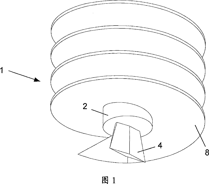
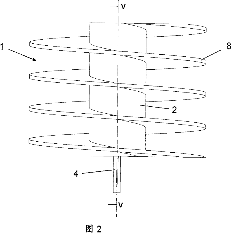
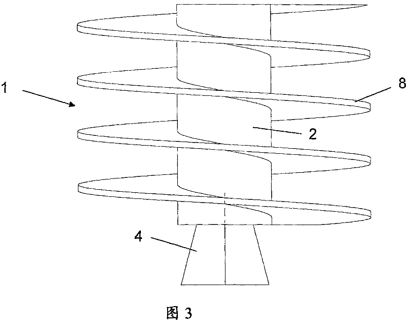
[0030] exist Figure 1 to Figure 5 The first extraction device shown in comprises an anchoring device 1 comprising a cylindrical anchoring body 2 with a cutting blade 4 at one end and a cylindrical hole 6 at the other end of the body. The profile shape of the cutting blade 4 is trapezoidal (American English: trapezoid) and the leading edge of the blade is sharpened so that it will cut into the ceramic foam filter. The hole 6 has an internal thread (not shown) forming connection means for connecting the extraction device to an insertion / extraction tool (not shown). The insertion / extraction tool may for example consist of a T-shaped bar with a thread at one end for engagement with an internal thread in the hole 6 . The insertion / extraction tool may also include lifting lugs for attachment to a crane or other lifting device.

[0031] An external helical thread 8 extends outwardly from the cylindrical surface of the anchor body 2 . In the embodiment shown in the figures, the he...


PUM

PropertyMeasurementUnit
distanceaaaaaaaaaa
depthaaaaaaaaaa
diameteraaaaaaaaaa

Abstract

An extraction device is provided for use when extracting a ceramic foam filter, as used for example in the production and processing of aluminium. The extraction device includes an anchor device (1) having an anchor body (2) suitable for driving into the filter, and a screw thread (8) that extends along at least part of the length of the anchor body, for engagement with the filter.

Description

technical field [0001] The present invention relates to a removal device for use in the removal of ceramic foam filters, for example in the production and processing of aluminum and other metals, and also to a method of removing ceramic foam filters using the removal device. Background technique [0002] Molten aluminum usually needs to be filtered before it is cast. The filtration process removes particulates that can cause waste in the finished product. [0003] Traditionally, ceramic foam filters are used. These ceramic foam filters are manufactured from a heat-resistant aluminum slurry by impregnating a reticulated foam that has been processed to a specific porosity with the slurry. The impregnated foam is then dried and fired in a drying oven. The foam evaporates leaving behind a porous ceramic body which is used as a filter. Ceramic filters come in a variety of sizes, typically: 7", 9", 12", 15", 17", 20", 23", and 26" wide, and 2" thick (16cm, 20cm, 27cm, 34cm, ...

Claims


Application Information

Patent Timeline
Patent Type & Authority Patents(China)
IPC IPC(8): F16B25/10C22B9/02C22B21/06
CPCF16B25/103C22B9/023C22B21/066Y10T29/49815Y10T29/53Y10T29/53687Y02P10/20
Inventor 马克·文森特
Owner PYROTECK INC
Learn More