Tuneable bushing

A bushing and sleeve technology, applied in the design features of spring/shock absorber, spring assembly composed of several springs, spring/shock absorber, etc., can solve the problems of time-consuming and expensive testing and manufacturing

Active Publication Date: 2008-06-18
孔斯贝格汽车公司
View PDF2 Cites 6 Cited by
  • Summary
  • Abstract
  • Description
  • Claims
  • Application Information

AI Technical Summary

Problems solved by technology

Testing and manufacturing of these large numbers of different bush

Method used


Image

  • Tuneable bushing
  • Tuneable bushing
  • Tuneable bushing

Examples


no. 1 example

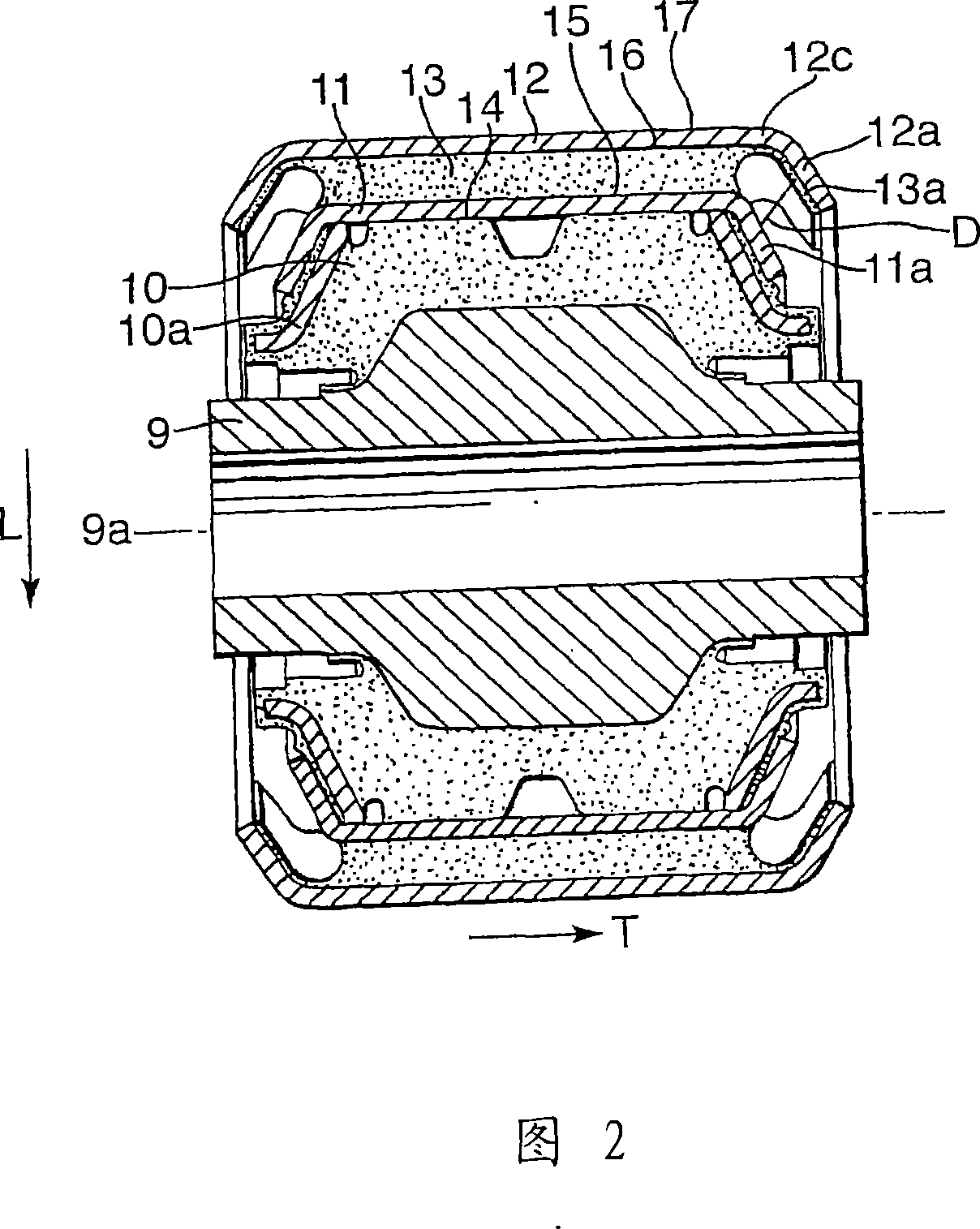
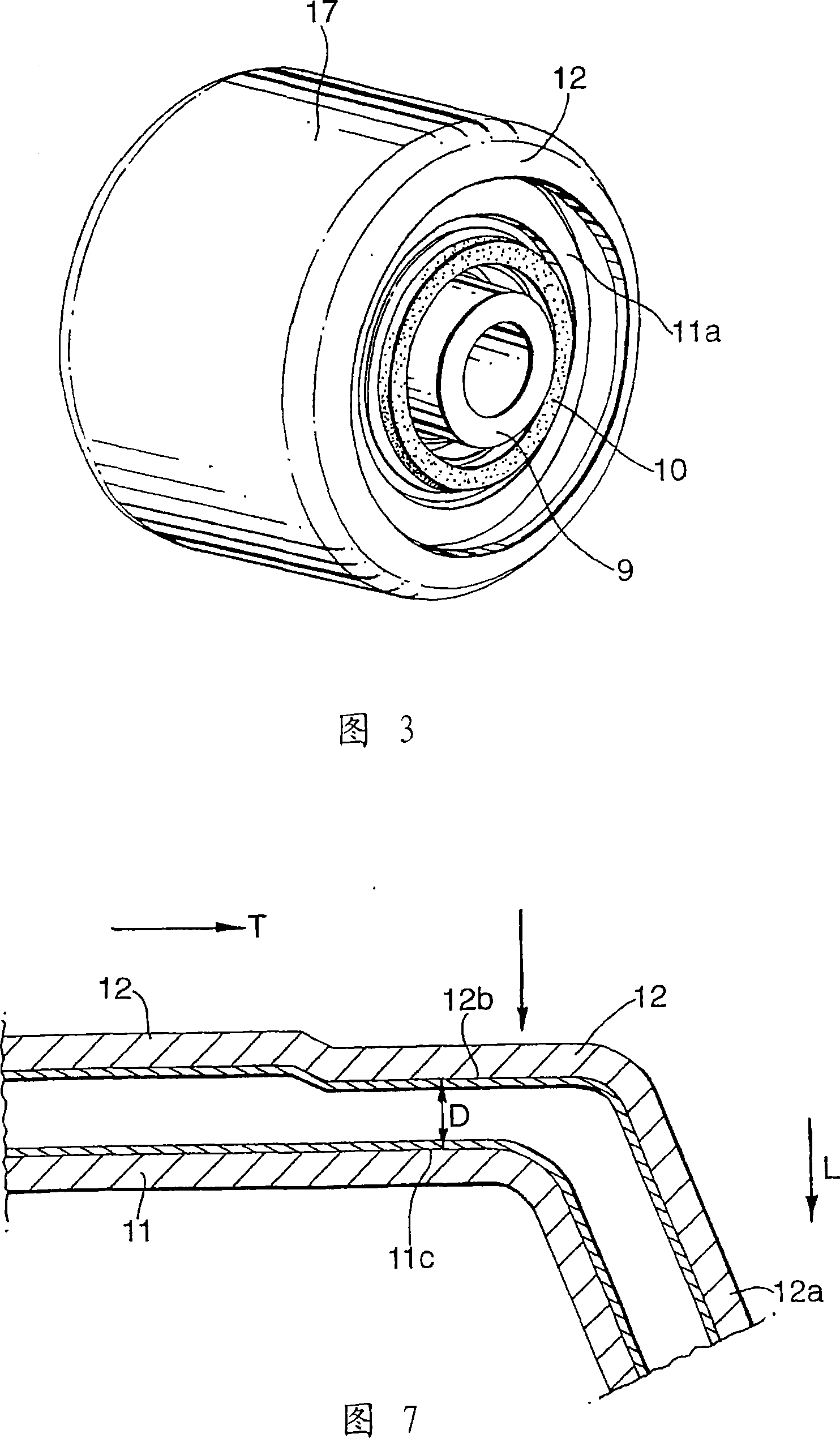
[0028]The first elastic member 10 is provided so as to be able to absorb displacement due to stress applied to the bushing arrangement in the vehicle transverse, longitudinal and vertical directions. Preferably, the first elastic member has appropriate rigidity in the vertical direction and softness in the transverse and longitudinal directions. The bushing arrangement 6a also comprises a second bushing element. The second bushing element comprises a second elastic element 13 and a second rigid sleeve 12 . The second rigid sleeve 12 is arranged radially spaced apart from the first rigid sleeve 11 and has a radially inner axial face 16 and a radially outer axial face 17 . The second elastic element 13 is arranged in the space between the first and the second rigid sleeve 11 , 12 . Alternatively, the second bushing element may be arranged somewhere between the first rigid sleeve 11 and the core 9, so as to be in a position radially closer to the central axis 9a of the core. A...


PUM


Abstract

A bushing arrangement for a connection between a cab and a vehicle chassis. The anti-roll bar consists of a torsion bearing and two connecting arms. Each link has a first end connected to the torsion bar and a second end connected to the core (9) through a first bushing element. The first bushing element comprises a first rigid sleeve (11) arranged concentrically with the core and a first elastic element (10) located between the first rigid sleeve and the core. The bushing device also includes a second bushing element arranged concentrically with the first bushing element and at a radially outer or inner position relative to the first bushing element. The second bushing element comprises a second rigid sleeve (12) and at least one second elastic element (13), wherein at least a portion of the radially inner surface of the second rigid sleeve is in contact with the radially outer surface of the second elastic element . The second elastic element is more elastic than the first elastic element. The second bushing element is provided with at least one adjustable detent means comprising a detent portion (12a) incorporated in the second bushing element.

Description

technical field [0001] The present invention relates to a bushing arrangement providing a connection between a cab and an anti-roll bar connected to the chassis of a vehicle. Background technique [0002] The cabin is exposed to forces such as vehicle rolling, vibrations from uneven road surfaces, and forces applied to the vehicle when cornering and braking. The anti-roll bar has a bushing arrangement to absorb vibration and transmit force. The elasticity of the bushing means determines the absorption capacity of the bushing means. The highly elastic bushing device satisfies the need for absorbing vibration or displacement, thereby providing vibration damping for the cab, while the highly rigid bushing device provides better contact with the road surface and provides better feedback to the driver. Furthermore, the bushing arrangement can be made flexible in some directions of the vehicle and stiff in other directions of the vehicle. [0003] WO03 / 062034 and EP525435 discl...

Claims


Application Information

Patent Timeline
IPC IPC(8): F16F3/093F16F1/387
CPCF16F1/387F16F3/093F16F2230/007B62D33/0604
Inventor 斯文·比约克加德
Owner 孔斯贝格汽车公司
Why Eureka
Try Eureka