Method of making an eyeglass lens

a technology of eyeglass lens and lens ring, which is applied in the field of eyeglass lens, can solve the problems of affecting the manufacturing precision of eyeglass lens, affecting the quality of eyeglass lens, so as to achieve the lowest possible manufacturing precision, the effect of varying the elasticity of a structural element and very fast conversion

Active Publication Date: 2017-12-26
SHAPE ENG GMBH
View PDF9 Cites 4 Cited by
  • Summary
  • Abstract
  • Description
  • Claims
  • Application Information

AI Technical Summary

Benefits of technology

[0038]Due to the variability of shape achieved in this way the method can be converted very quickly under computer control to different eyeglass frame types with the respective structural elements. In this case it is not necessary to change a tool or to change a nozzle.
[0039]In contrast to the previously known methods, such as are described in patent DE 100 50 007, the method according to the invention makes it possible to vary the profile cross-section over the circumference of the lens.
[0040]For example, one may vary the elasticity of a structural element by changing the cross-sectional shape according to the location, for example in order to achieve the least possible manufacturing precision for the production of the frame and lens edge, with at the same time freedom of movement of the connection.

Problems solved by technology

Although in CNC-controlled eyeglass lens edge-grinding machines it is possible for the facet contour of a facet to be ground conform to the contour of the faceted groove of a selected eyeglass frame, the eyeglass lens with the ground facets is completely inelastic, so that stresses from the eyeglass frame are transmitted to the eyeglass lenses during installation.
Due to temperature changes stresses can also be produced that in particular plastic lenses are sensitive to and that tend to cause cracks.
Furthermore, the grinding of a facet represents an additional operation that in particular considerably prolongs the automated edge machining because of the necessary precision.
The methods and concepts shown in the cited publications have not been successful hitherto on the market, in spite of the advantages by comparison with the prior art.
This is cause inter alia by the following points:The handling of separate profiled strips and bonding adhesives is difficult in practice and significantly increases the complexity of the machines.The shape of the glued or extruded profiled strands cannot be easily adapted to different geometries of the frame groove.Eyeglass lenses can have very thin edge regions locally, the application of a profiled strand in these regions is difficult, and projection of the profiled section over the edge of the eyeglass lens is not accepted.The long-term durability and load-bearing capacity of compositions with contact adhesives, such as used in profiled strips, is critical taking into account the environmental influences (sunlight, sweat).

Method used


Image

  • Method of making an eyeglass lens
  • Method of making an eyeglass lens
  • Method of making an eyeglass lens

Examples


Embodiment Construction

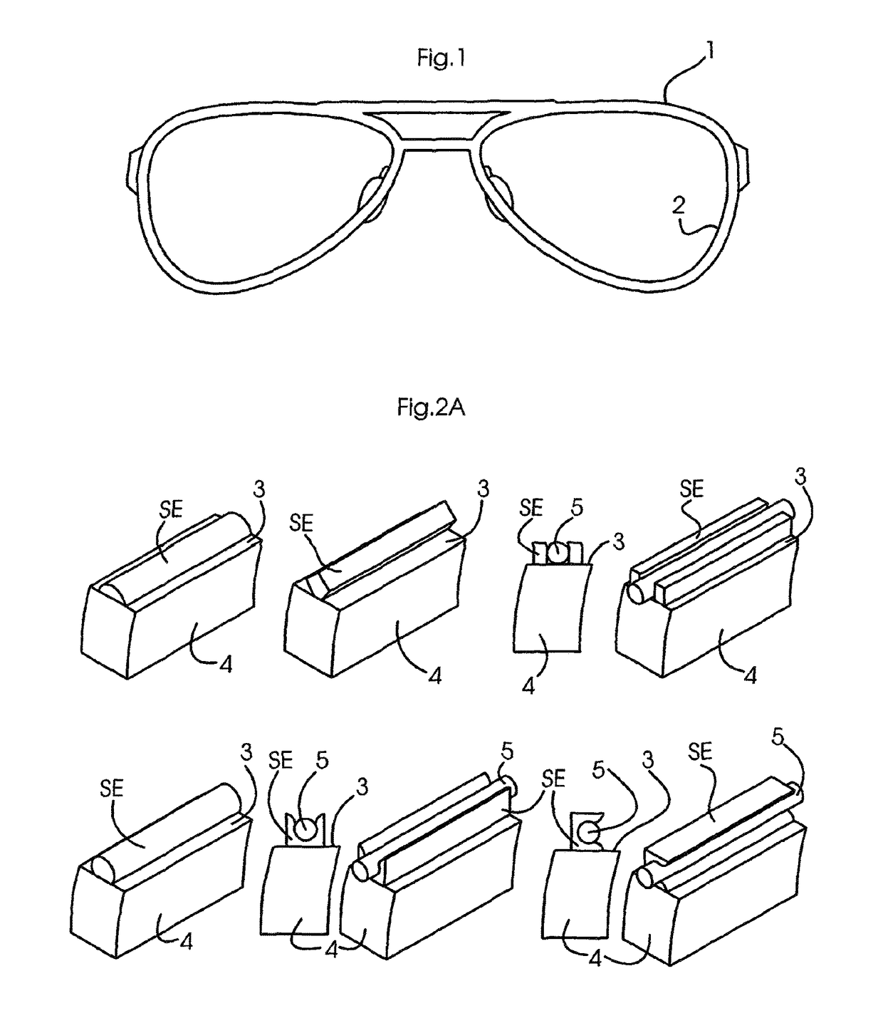
[0065]FIG. 1 shows a full-rim frame 1 that has on the inside of the rim 2 a predetermined shape (not shown here), generally a facet to receive a corresponding shape on an edge 3 of an eyeglass lens 4 of suitable shape.

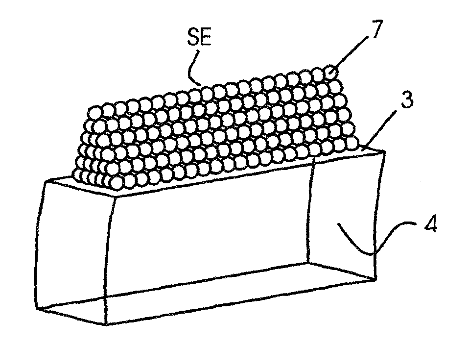
[0066]For such a frame, corresponding structural elements SE, that either correspond to the shape of the frame rim or adapt thereto due to flexibility, are arranged on the edge 3 of an eyeglass lens 4.

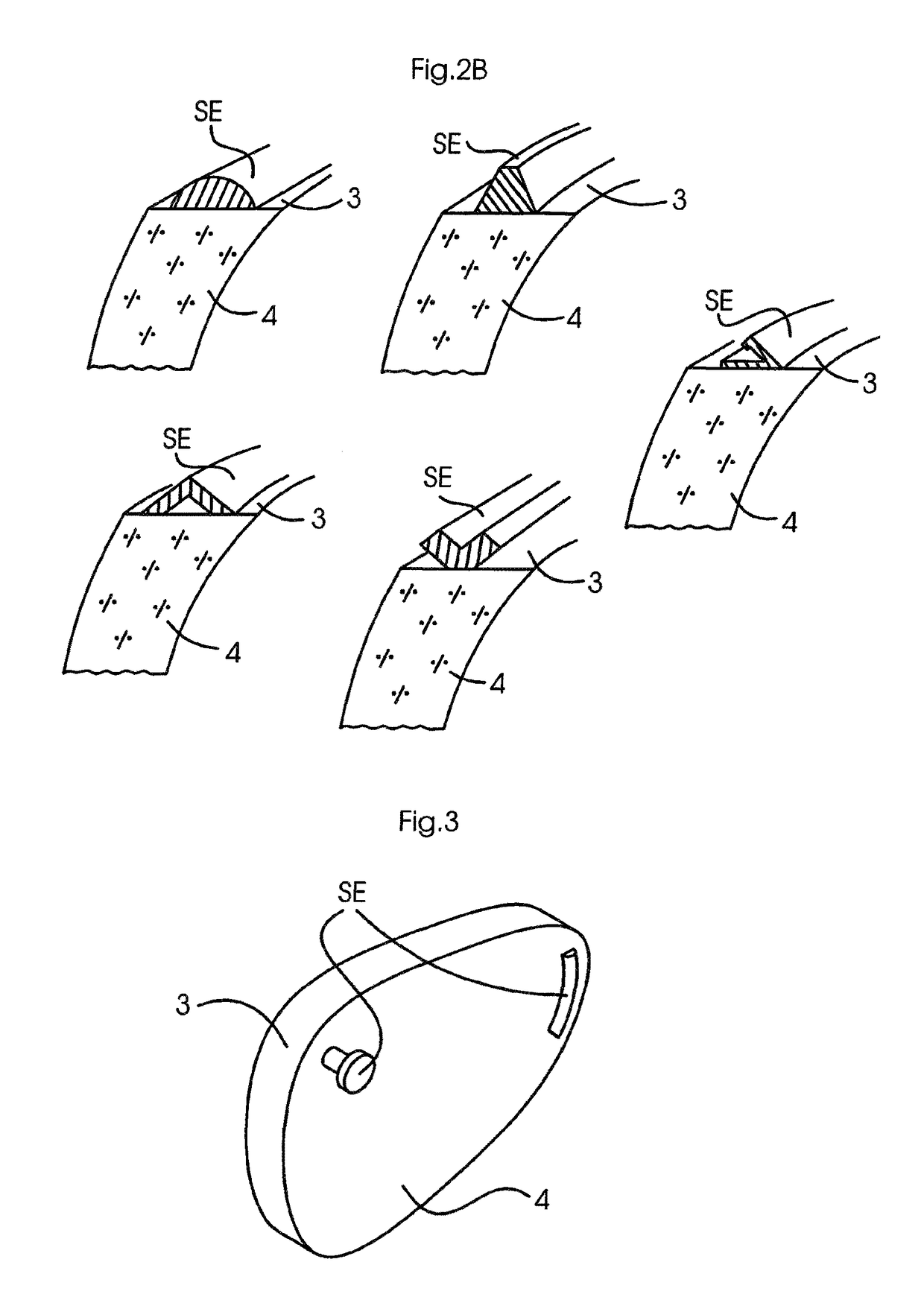
[0067]FIGS. 2A and 2B show a large number of possible shapes of structural elements SE that are provided for application to the lens edge 3 of an eyeglass lens 4, as described in the introduction. In this case the forms 1, 2 and 4 of FIG. 2A and the forms of FIG. 2B are suitable for use in a full-rim frame.

[0068]The forms 3, 5 and 6 of FIG. 2A show structural elements SE that are provided to receive Nylon filaments 5. For this purpose, they form, on their own or at least in conjunction with the edge, seat grooves into which the filament 5 can be laid.

[0069]FIG. 3 shows ra...


PUM

PropertyMeasurementUnit
shapeaaaaaaaaaa
viscosityaaaaaaaaaa
shear forceaaaaaaaaaa

Abstract

The invention relates to a spectacle lens (3) which comprises at least one structural element (SE) on the outer edge (4) and/or the front or rear surface thereof, wherein the at least one structural element (SE) is formed by a material which is applied in liquid form on the edge (3) and/or the front/rear surface of the spectacle lens (4), is connected in a bonded manner to the lens and is hardened chemically or by radiation. The invention further relates to a method for the production thereof.

Description

CROSS REFERENCE TO RELATED APPLICATIONS[0001]This application is the US-national stage of PCT application PCT / EP2014 / 003115 filed 21 Nov. 2014 and claiming the priority of German patent application 102014000107.5 itself filed 10 Jan. 2014.BACKGROUND OF THE INVENTION[0002]The invention relates to an eyeglass lens, in particular one having a cross-section perpendicular to the optical axis that corresponds to an eyeglass lens opening in a selected eyeglass frame or, in the case of rimless or partially framed eyeglasses, to a selected shape, and having at least one structural element applied to the eyeglass lens, preferably on outer and / or front or rear face. The invention relates to a method of making such an eyeglass lens.[0003]Such a structural element can, for example, connect the eyeglass lens and the eyeglass frame according to the known prior art.[0004]Moreover, at least in the case of eyeglasses that are customized for the eyeglass wearer by an optician, the eyeglass lens is cen...

Claims


Application Information

Patent Timeline
Patent Type & Authority Patents(United States)
IPC IPC(8): G02C7/02G02C5/12B29D11/00G02C1/00G02C5/02
CPCG02C1/10G02C5/12G02C5/02B29D11/00432B33Y80/00B29D11/00009B29D11/00865
Inventor LUDERICH, JOERGFRINGS, DAVIDPOEPPERL, CHRISTIAN
Owner SHAPE ENG GMBH
Why Eureka
Try Eureka