Occupant restraint device

An occupant restraint, air bag technology for pedestrian/occupant safety arrangements, transportation and packaging, special locations of vehicles, etc.

Inactive Publication Date: 2008-07-02
TAKATA CORPORATION
View PDF2 Cites 3 Cited by
  • Summary
  • Abstract
  • Description
  • Claims
  • Application Information

AI Technical Summary

Problems solved by technology

Therefore, the seat air bag has the potential to inflate further upwards than the inflated auxiliary air bag

Method used


Image

  • Occupant restraint device
  • Occupant restraint device
  • Occupant restraint device

Examples


Embodiment Construction

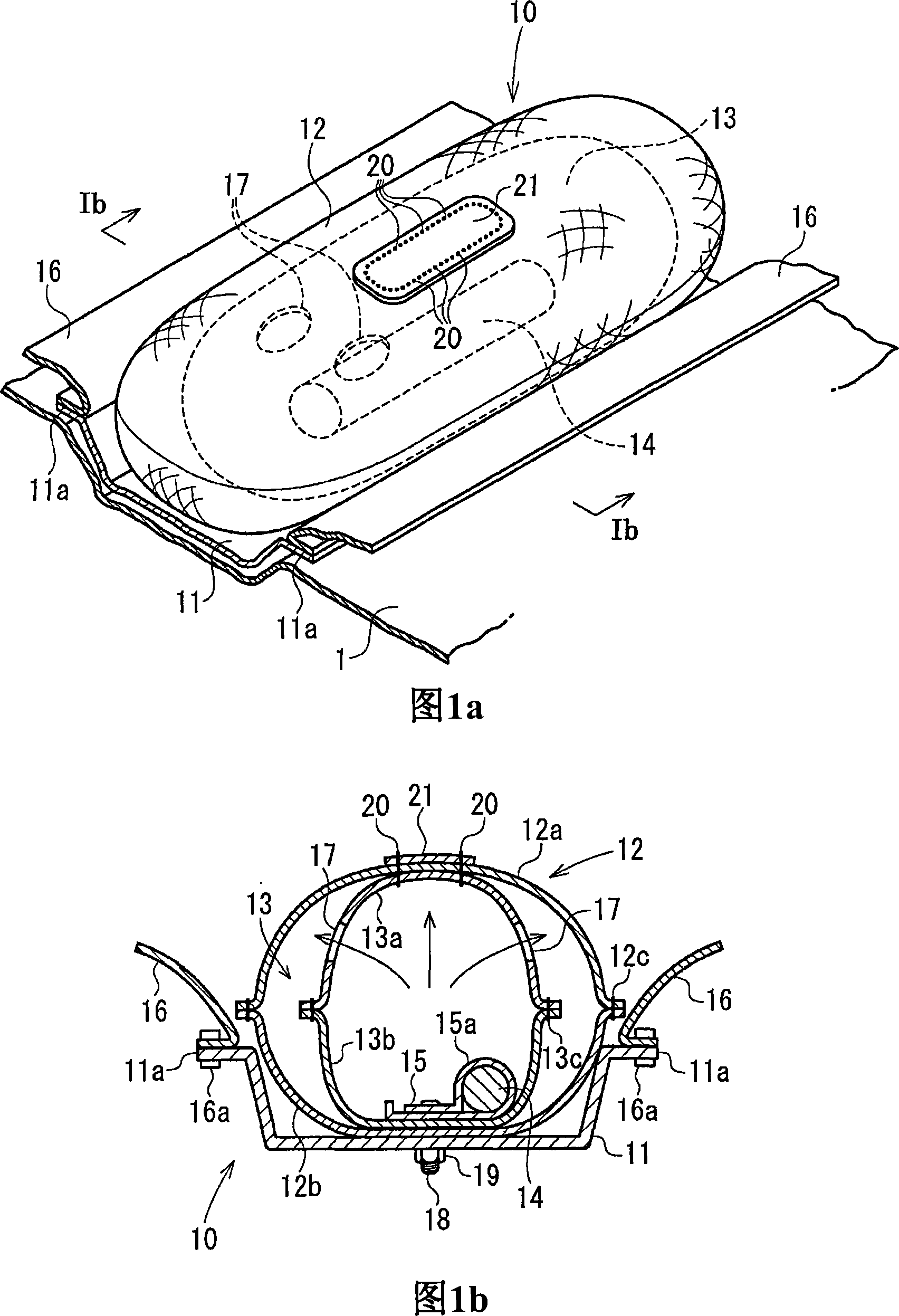
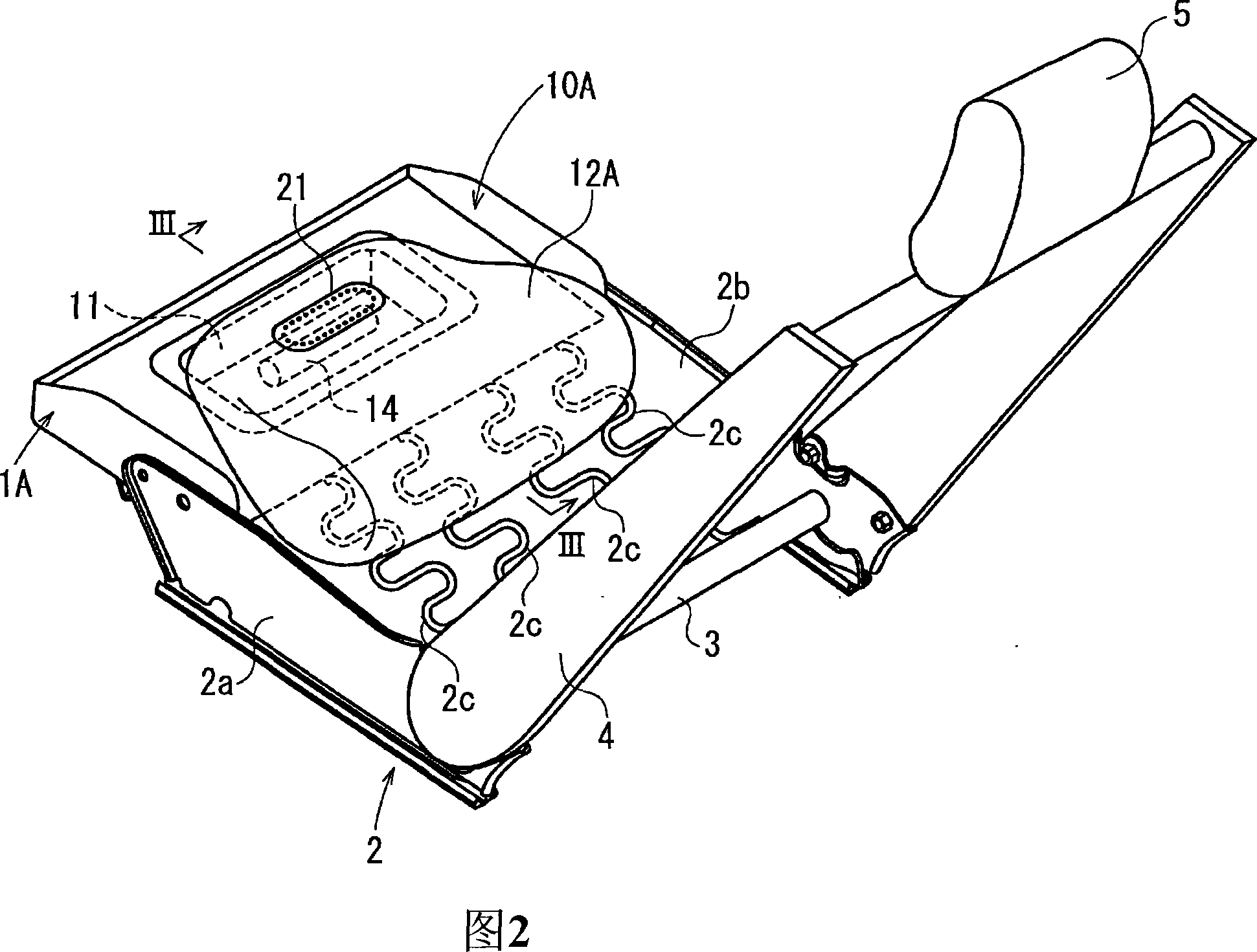
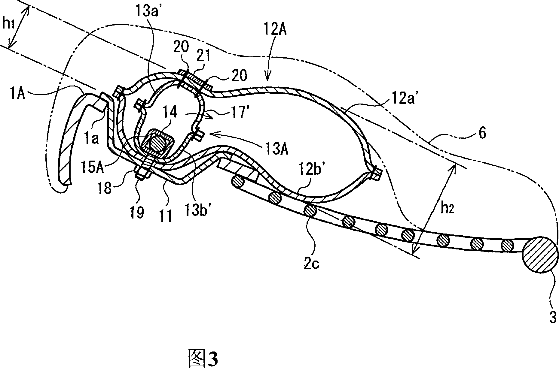
[0012] In the occupant restraint device of the present invention, in an emergency such as a vehicle collision, after the inflator performs a gas ejection operation, the gas is supplied from the inflator into the inner air bag, the inner air bag is inflated, and the air in the inflator Gas flows out from the outflow portion into the seat bag, thereby inflating the seat bag. The seat cushion is pushed up from the bottom by the inflated seat air bag, or is compressed and hardened by the upward pushing force, thereby preventing or restraining the occupant's waist from moving forward ("submersion" phenomenon).

[0013] In the present invention, the inner air bag is inflated earlier than the seat air bag by the high-pressure gas supplied from the inflator, and the seat air bag is inflated thereafter.

[0014] In the present invention, the lower part of the inner air bag is connected to the lower part of the seat cushion, and the upper part is connected to the upper part of the seat ...


PUM


Abstract

An occupant restraint device in which the amount of upward inflation of a seat bag is limited. The occupant restraint device (10) has the seat bag (12) extending in the direction of left-right width direction of a seat and inflatable to press a seat cushion from the underside; a retainer (11) placed on a seat pan (1); an inner bag (13) placed in the seat bag (12); and an inflator (14) for inflating the seat bag (12) and the inner bag (13). The inner bag (13) is connected at its lower part to the retainer (11) and at its upper part to the upper part of the seat bag (12).

Description

technical field [0001] The present invention relates to an occupant restraint device for restraining occupants on seats of vehicles such as automobiles during a collision, in particular to an occupant restraint for restraining the occupant's waist and preventing the occupant's body from moving forward and downward during a forward collision device. Background technique [0002] As a system for restraining the occupants of a car during a collision, in order to prevent the phenomenon of "submerging" from the underside of the belt in the event of a frontal collision even if the occupant is wearing a seat belt, JP-A-2004-338514 describes the following Occupant restraint device: An inflatable seat air bag (referred to as an air bag main body in the same gazette) is disposed between the seat cushion and the seat pan, and the seat cushion is pushed up by inflating the seat air bag during a vehicle collision The front part of the seat air bag, wherein an auxiliary air bag is arrang...

Claims


Application Information

Patent Timeline
Patent Type & Authority Applications(China)
IPC IPC(8): B60R21/20B60N2/42B60R21/02B60R21/16B60R21/207
CPCB60R21/207B60R2021/23324B60N2/42763B60R21/2346B60R21/231B60N2/42718
Inventor 熊谷雅义吉川浩通越川公裕
Owner TAKATA CORPORATION
Why Eureka
Try Eureka