Rolling guide device and method of manufacturing the same

A technology of rolling guidance and manufacturing method, applied in the direction of linear motion bearings, bearings, bearing components, etc., can solve the problems of increased processing time and the number of parts, long processing time, and troublesome assembly of sliding parts.

Inactive Publication Date: 2008-07-02
THK CO LTD
View PDF2 Cites 4 Cited by
  • Summary
  • Abstract
  • Description
  • Claims
  • Application Information

AI Technical Summary

Problems solved by technology

[0008] However, in this conventional rolling guide device, the processing man-hours of the blocks constituting the sliding member are many, and the problem of low reliability of processing accuracy tends to occur.
In addition, not only the processing man-hours of the block are many, but also the end caps for forming the circular circulation path of the balls are required, the processing man-hours and the number of parts increase, and the manufacturing cost of the sliding parts increases.
In addition, in order to make the circulation of the balls in the annular circulation path flexible, the end cap must be attached to the block with high precision, so the assembly of the sliding parts is also troublesome.

Method used


Image

  • Rolling guide device and method of manufacturing the same
  • Rolling guide device and method of manufacturing the same
  • Rolling guide device and method of manufacturing the same

Examples


Embodiment Construction

[0026] Next, the rolling guide device of the present invention will be described in detail with reference to the drawings.

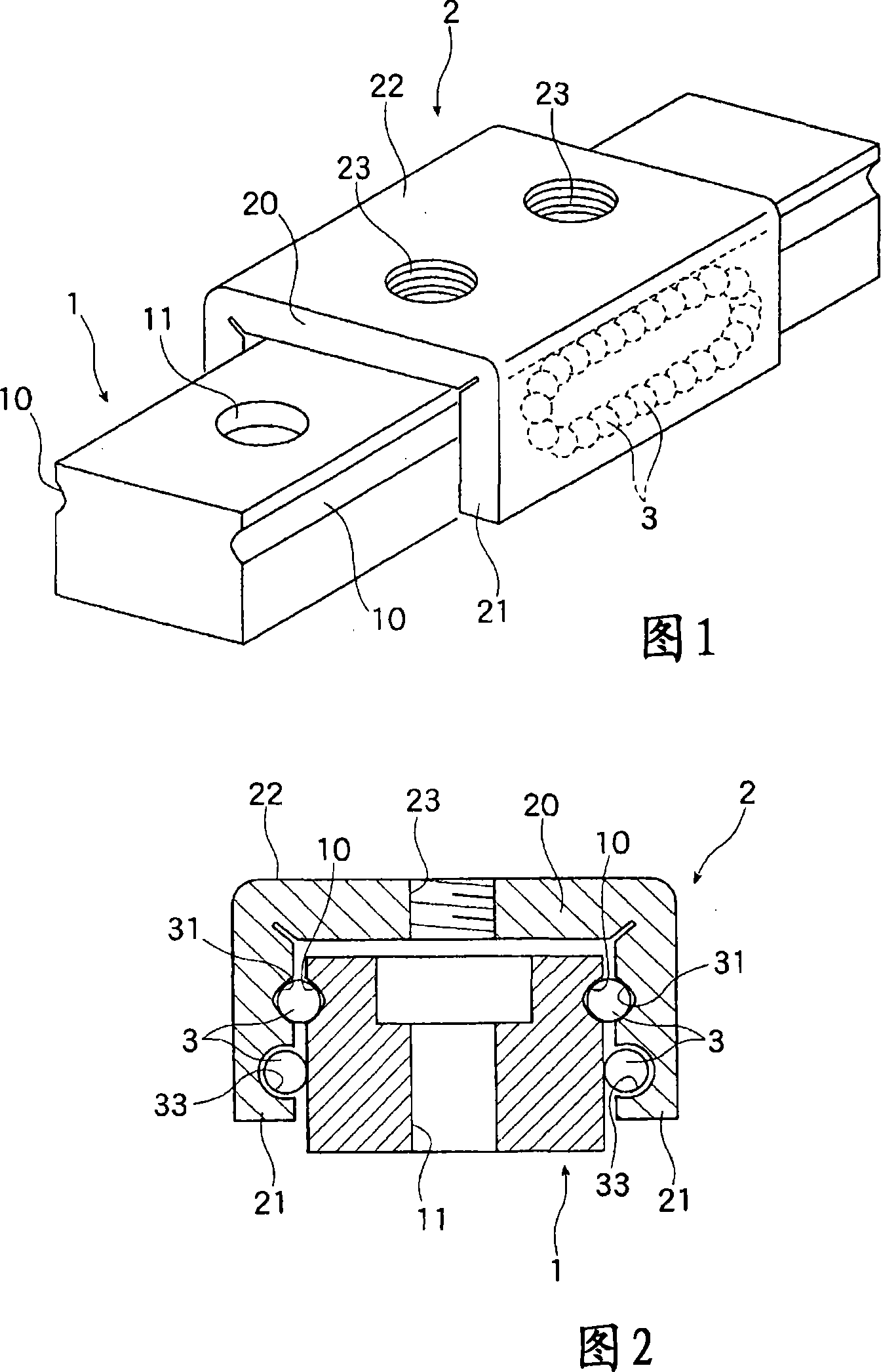
[0027] 1 and 2 show a first embodiment of a rolling guide device to which the present invention is applied. The rolling guide device according to the first embodiment is composed of a long track rail 1 having a substantially rectangular cross section, and a slide member 2 formed in a tunnel shape and assembled to the track rail 1 via a plurality of balls 3 . The above-mentioned sliding member 2 can freely reciprocate on the track guide rail 1 while straddling the track guide rail 1 .

[0028] On both side surfaces of the track guide rail 1, one rolling groove 10 for each ball 3 is formed in the longitudinal direction. In the rolling groove 10, two rolling surfaces on which the ball 3 rolls intersect at 90 degrees, and the cross section thereof is formed in a so-called Gothic arch shape. Therefore, the ball 3 is in two-point contact with the rolling gro...


PUM


Abstract

The rolling guide device of the present invention can reduce the number of parts and components when forming the sliding part (2), reduce the processing man-hours, and be manufactured easily and at low cost. It is assembled on the track guide rail (1) and the track guide rail ( The sliding part (2) on 1) is formed, and the sliding part (2) is formed by bending the metal plate part (5), and has a transverse web (20) and a pair of flange parts (21) formed in a tunnel shape, and each wing A track groove (30) for the ball (3) to circulate is formed on the edge (21), and the track groove (30) includes: a load linear groove (31) where the ball (3) rolls while bearing a load, and a handle on the load line The ball (3) rolling over in the groove (31) is released from the load state and a pair of ball deflection grooves (34) that make its direction change, and the ball (3) is transferred from one ball deflection groove (34) to The other side of the ball deflection groove (34) is constituted by an unloaded linear groove (33).

Description

technical field [0001] The present invention relates to a rolling guide device. In the rolling guide device, a track guide rail and a sliding part are assembled together by a plurality of balls, and a loaded object fixed on the above-mentioned sliding part can freely reciprocate along the track guide rail. In particular, it relates to a rolling guide device in which the above-mentioned sliding member has an annular circulation path for balls and is capable of continuously moving the sliding member along a track rail while circulating the balls in an annular manner, and a method for manufacturing the same. Background technique [0002] In work tables of machine tools and linear guides of various conveying devices, rolling guides in which sliding members on which movable bodies such as work tables are mounted continuously move along track rails are often used. In this rolling guide device, the above-mentioned sliding member is assembled on the track guide rail with a plurality...

Claims


Application Information

Patent Timeline
Patent Type & Authority Applications(China)
IPC IPC(8): F16C29/06
CPCF16C29/005F16C29/0602F16C29/063F16C29/0633F16C33/588Y10T29/49641F16C33/02F16C33/06F16C35/02
Inventor 白井武树
Owner THK CO LTD
Why Eureka
Try Eureka