
Explosion-proof inductive voltage transformer

a voltage transformer and inductive technology, applied in transformers, electrical components, electrical apparatus, etc., can solve the problems of high cost, complicated manufacturing and installation, and high electrical stress of inductive voltage transformers, so as to reduce the electrical stress of its surroundings, prevent or reduce the damage to the inductive voltage transformer, and the effect of low cos

Active Publication Date: 2019-11-21
ARTECHE NORTH AMERICA S A DE CV
View PDF4 Cites 0 Cited by
  • Summary
  • Abstract
  • Description
  • Claims
  • Application Information

AI Technical Summary

Benefits of technology

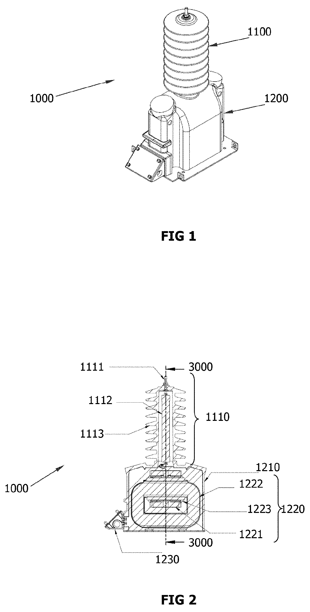
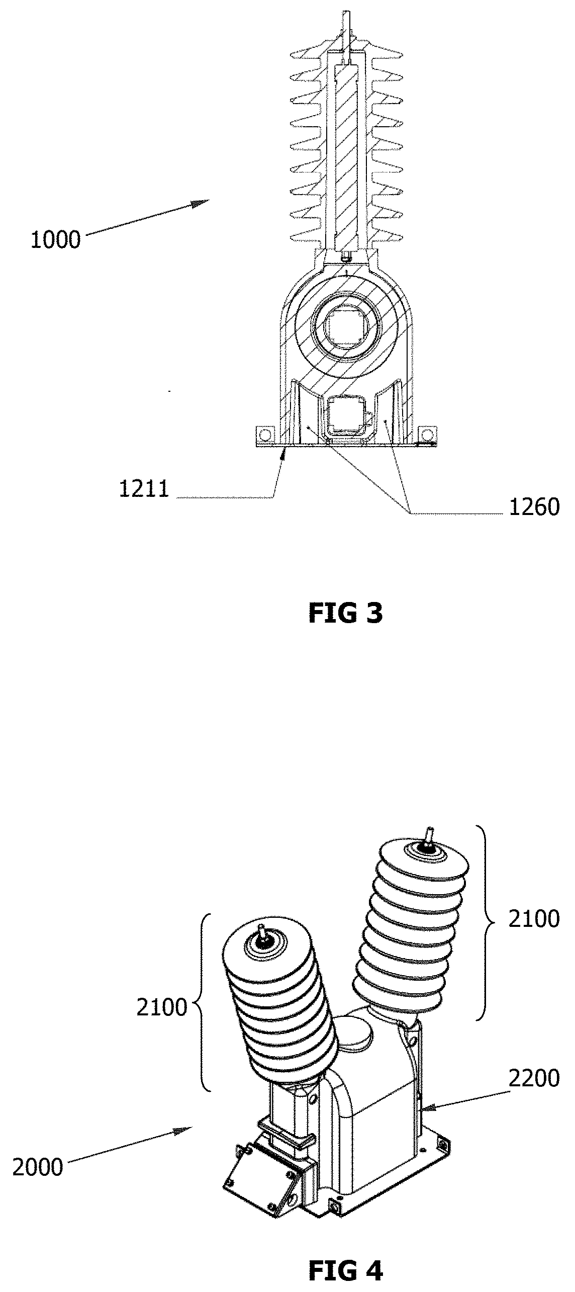
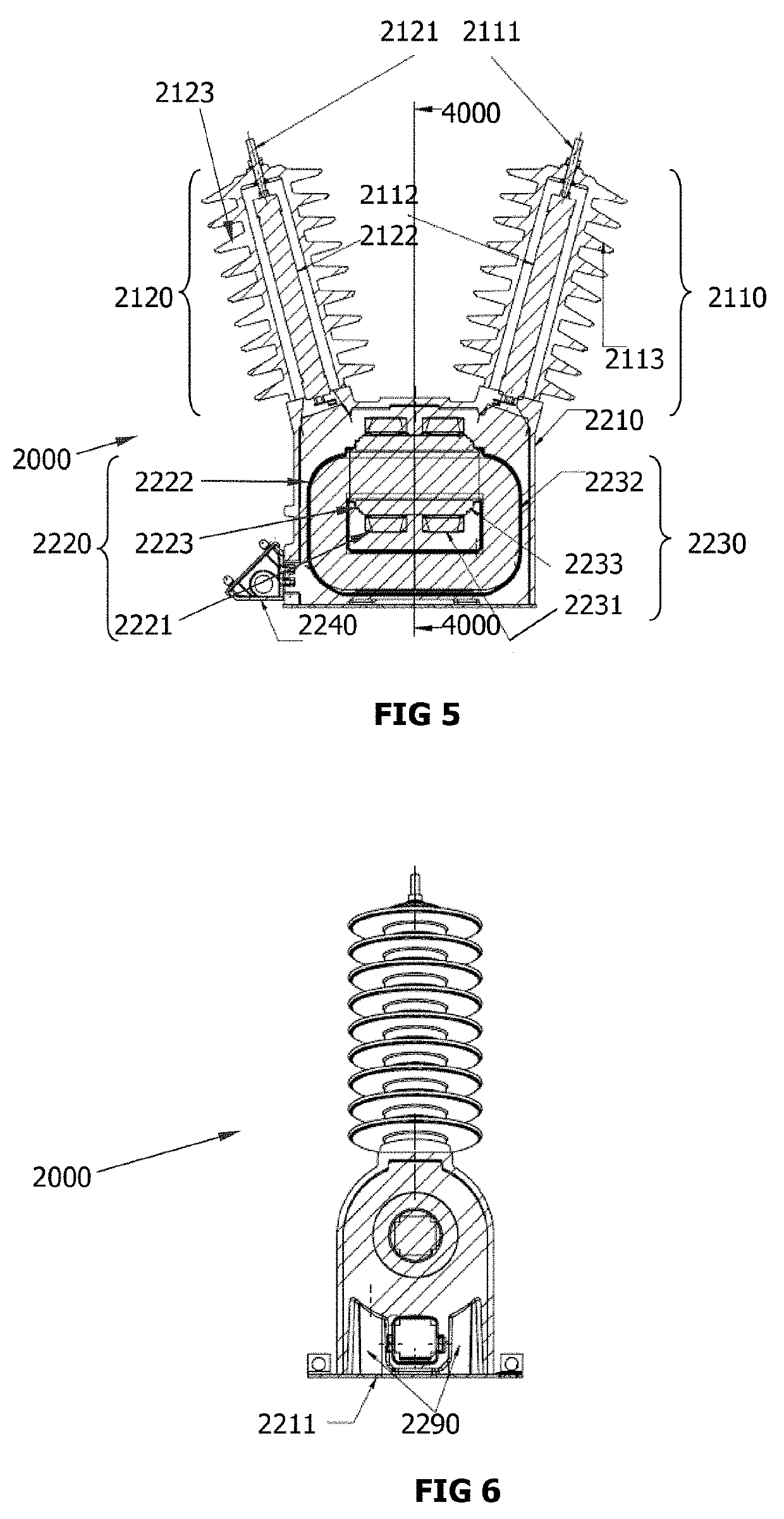
The present invention provides an easy and low cost way to prevent damage to an IVT and its surrounding in case of an explosion caused by electrical failure. The shock mitigation means help to direct the gases and shockwave of the explosion towards two hollow sections, reducing the damage caused by the explosion to the IVT and its surroundings. The IVT comprises a high voltage section and a voltage transforming section, which are protected by an insulation body to minimize the impact of explosions in case of electrical failure.

Problems solved by technology

Nowadays, inductive voltage transformers (IVT) have some problems related to electrical failures.
For instance, they are prone to explosions due to a short circuit, ferroresonance occurrences, a power surge, or an internal electric arc or internal arc discharge.
However, these special chambers are complicated to manufacture and to install, as well as very expensive.
Moreover, these chambers only protect the nearby facilities, but they do not offer protection to the transformer itself, resulting in a partial or complete destruction of the transformer after a failure occurs.
The shell protects and insulates on the outside but it does not prevent an explosion neither protect the transformer of the mechanical stress caused by the explosion.
However, this results in having to create a special infrastructure to be able to submerge the transformer that is costly and difficult to install.
On another note, the transformer of document US2014232509 integrates an electrostatic shield for controlling electrostatic field stress, but this only protects the transformer against discharges and leaves it vulnerable to other electrical failures.

Method used


Image

  • Explosion-proof inductive voltage transformer
  • Explosion-proof inductive voltage transformer
  • Explosion-proof inductive voltage transformer

Examples


example 1

[0058]This example shows an electrical failure analysis through finite elements calculation made by the software “COMSOL Multiphysics® 5.0” in order to determine the probability of a failure during a sustained short-circuit in an IVT.

[0059]The IVT used in the analysis are shown in the following table. The IV transformer SMM-B-CW, IVT SMM-LME-CW and IVT SMM-LME-SHCEP are different embodiments according to the present invention.

TABLE 1Type ofType ofShock mitigationinsulationinsulationNamemeans(internal)(external)IVT B-HNoBCWIVT LME-HNoLMECWIVT LME-SHCEPNoLMES-HCEPIVT SMM-B-HYesBCWIVT SMM-LME-HYesLMECWIVT SMM-LME-SHCEPYesLMES-HCEP

TABLE 2Type ofinsulationFeaturesBUnmodified, solvent-free, bisphenol A based epoxy resinLMEModified, solvent-free, low viscous epoxy resin basedon bisphenol ACWCycloaliphatic, hot-curing, epoxy resinS-HCEPHydrophobic, cycloaliphatic epoxi resin

[0060]Now, FIG. 7 shows the von Mises stress when a failure caused by the sustained short-circuit occurs, FIG. 7a show...

example 2

[0064]This example shows the mitigation of the damage caused by a short-circuit to the explosion-proof IVT of the present invention with shock mitigation means but no current limiting element.

[0065]The high voltage section of the transformer is supplied with a voltage equal to the nominal value of 22,000 / V3 V and the secondary terminals are short-circuited. The voltage and current is kept constant for about 120 seconds, at this point the primary current increases abruptly due to an internal fault in the IVT, the gases of the explosion caused by the failure are released through the shock mitigation means. After the explosion the transformer has a crack in the lower part but there is no visible fracture in the external body. FIG. 10 shows the bottom view of the IVT (2000), the base (2211) and the shock mitigation means (2290) before the explosion and FIG. 11 shows the bottom view of the IVT (2000), the base (2211) and the shock mitigation means (2290) after the explosion.

example 3

[0066]This example further shows the mitigation of the damage caused by a short-circuit to the explosion-proof IVT of the present invention with both shock mitigation means and current limiting element.

[0067]The high voltage section of the transformer is supplied with a voltage equal to the nominal value of 22,000 / V3 V and the secondary terminals are short-circuited. The tension is kept constant for 180 seconds (9000) and the IVT interrupts the current at second 75 (10000), no damages were caused to the IVT. The above mentioned is shown in FIG. 12.


PUM


Abstract

An explosion-proof inductive voltage transformer (IVT) of the type comprising: i) a high voltage section that receives a high voltage current, limits and insulates the high voltage current to be transformed and reduces its electrical stress; and, ii) a voltage transforming section connected to the high voltage section and contained in an insulation body in order to protect the elements of the voltage transforming section and reduce the impact of explosions in case of electrical failure, wherein the voltage transforming section comprises means for reducing the voltage of the high voltage current to a low voltage and electric transmission means that transmit a resulting low voltage current to a low voltage distribution line; wherein the voltage transforming section of the IVT further comprises shock mitigation means comprising at least one hollow section located opposite the high voltage section that, during an electrical failure causing an explosion, direct the gases and shockwave of the explosion towards the hollow section, thereby reducing the damage caused by the explosion to the IV transformer and its surroundings; provides an explosion-proof inductive voltage transformer easy to install and with a low cost manufacture.

Description

FIELD OF THE INVENTION[0001]The present invention is related to electrical devices, and more particularly it is related to an explosion-proof inductive voltage transformer.BACKGROUND OF THE INVENTION[0002]Inductive Voltage Transformers (IVT), are used for voltage metering and protection in high or medium voltage network systems and they are designed to provide a scaled down replica of the voltage in the high or medium voltage line and isolate the measuring instruments, meters, relays, etc., from the high voltage power circuit. They transform the high or medium voltage into low voltage adequate to be processed in measuring and protection instruments secondary equipment, such as relays and recorders.[0003]Nowadays, inductive voltage transformers (IVT) have some problems related to electrical failures. For instance, they are prone to explosions due to a short circuit, ferroresonance occurrences, a power surge, or an internal electric arc or internal arc discharge.[0004]Currently some I...

Claims


Application Information

Patent Timeline
IPC IPC(8): H01F27/40H01F27/02H01F27/06
CPCH01F27/402H01F27/022H01F27/06H01F38/26H01F27/327
Inventor VENEGAS VEGA, MARCO ANTONIOESTRADA CARBAJAL, JUAN PABLO
Owner ARTECHE NORTH AMERICA S A DE CV
Learn More