Axle coupler dedicated tester and method of use thereof

A coupling and tester technology, applied in instruments, measuring devices, mechanical devices, etc., can solve problems such as troublesome production and safety, difficult to detect couplings, deformation of coupling shafts, etc., and achieve simple use and test results. Good, low wear effect

Active Publication Date: 2008-07-09
CHINA CAMC ENG
View PDF0 Cites 12 Cited by
  • Summary
  • Abstract
  • Description
  • Claims
  • Application Information

AI Technical Summary

Problems solved by technology

Because only one meter is used, it is not easy to directly detect the skew of the coupling, so it is not easy to detect unqualified couplings, and it is easy to deform and break the connected shaft, which brings many unnecessary troubles to production and safety.

Method used


Image

  • Axle coupler dedicated tester and method of use thereof
  • Axle coupler dedicated tester and method of use thereof
  • Axle coupler dedicated tester and method of use thereof

Examples


Embodiment 1

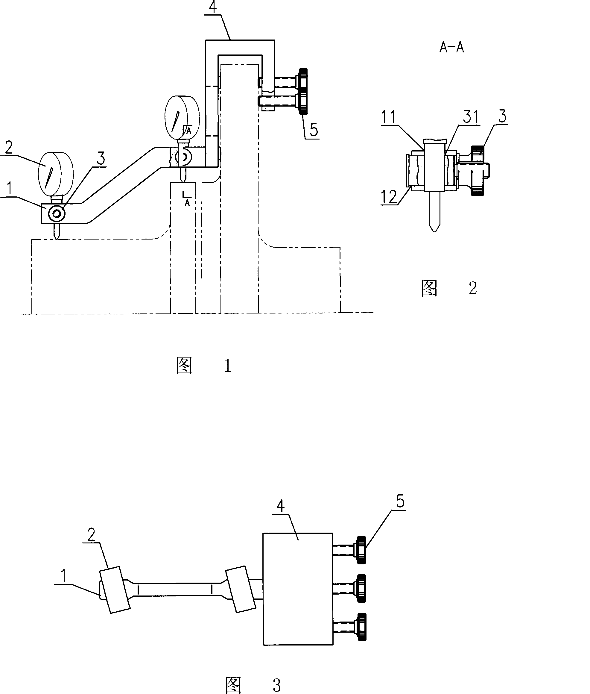
[0046] As shown in Figures 1, 2, and 3, a special tester for couplings is composed of a dial gauge support frame 1, a dial gauge 2, an adjustment knob 3, a fixing frame 4 and a fixing knob 5. The sub-meter support frame 1 and the fixed frame 4 are fixed together; the dial indicator support frame 1 is stepped, and the two steps are respectively provided with mounting holes 11, and the direction perpendicular to the axis of the mounting hole 11 is provided with accommodating adjustment The lateral hole 12 of the knob; the adjusting knob 3 is provided with a pin hole 31 corresponding to the mounting hole and having the same diameter, and the dial indicator 2 is fixedly arranged in the mounting hole 11 and the pin hole of the corresponding adjusting knob 12; the fixed frame 4 is a Π-shaped slot-type structure, one end of the Π-shaped slot is fixedly connected with the dial indicator support frame 1, and two rows of fixed knobs 5 are arranged on the other end surface, for a total of...

Embodiment 2

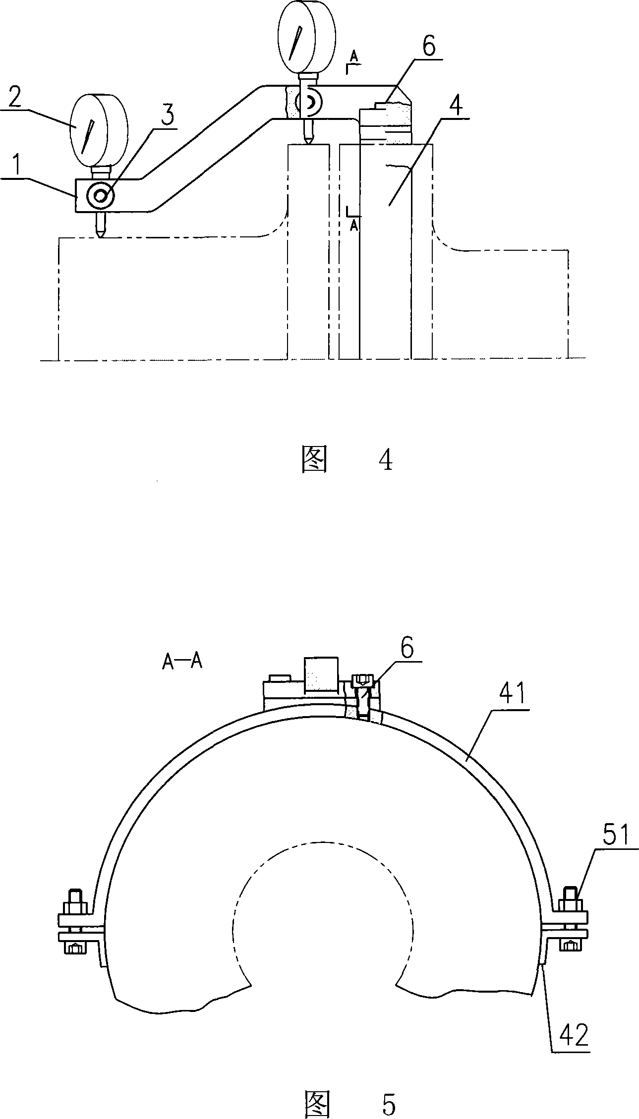
[0056] As shown in Figures 4 and 5, the difference from Embodiment 1 is that the fixed frame 4 is a hoop structure, and the hoop is composed of two semicircular rings 41, 42 fixed by fixing screws 51; The dial indicator support frame 1 is fixedly arranged on the upper part of the upper semicircle 41 of the clamp by screws 6 .

[0057] The test steps when testing ordinary couplings are as follows:

[0058] ① Connect the two halves of the coupling together through a pin;

[0059]②Fix the hoop of the fixed frame 4 on a half-coupling by pre-tightening the two half rings 41 and 42 through the fixing screw 51, and insert the two dial indicator rods into the installation hole and the corresponding adjustment knob pin hole , so that the test heads of the two dial gauges are respectively pressed against the rim and hub of the other half of the coupling, and the pre-tightening adjustment knob is used;

[0060] ③ Check the installation position of the dial indicator 2, and tighten the ...

Embodiment 3

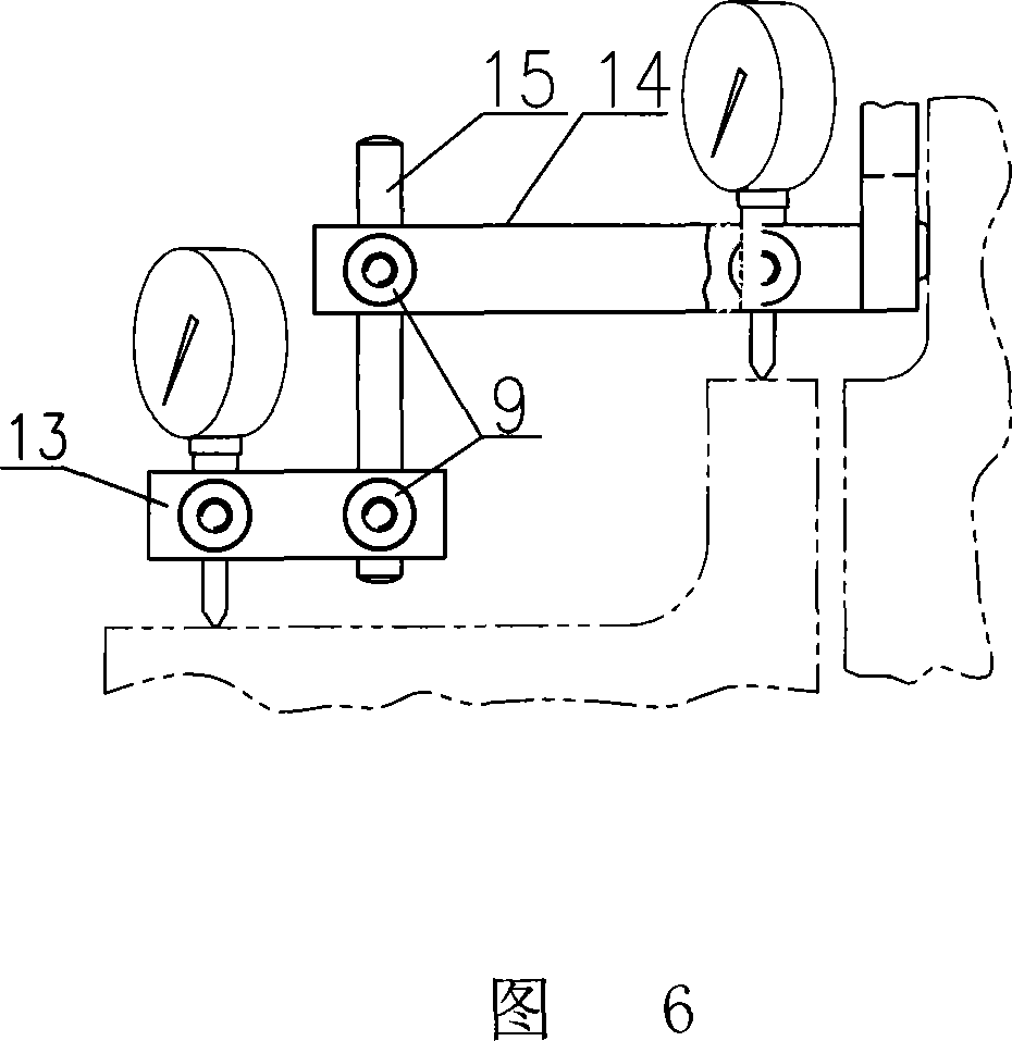
[0065] As shown in Figure 6, the dial indicator support frame is a connecting rod structure fixedly arranged by an adjusting knob, including two transverse connecting rods 13, 14 and a longitudinal rod connecting 15 connected thereto, and the two transverse connecting rods 13 , 14 in the same vertical plane, two mounting holes are respectively arranged on the two transverse connecting rods 13, 14, the longitudinal connecting rod 15 is penetrated in one of the mounting holes, and on the side perpendicular to the axis of the mounting hole Adjusting knobs 9 are arranged on each of them, and a pin hole concentric with the installation hole is arranged on the said adjustment knob; a dial indicator is installed in the other installation hole.

[0066] When testing a common coupling whose height difference between the hub and the rim is a non-standard value, the test steps are as follows:

[0067] ① Connect the two halves of the coupling together through a pin;

[0068] ②Fix the fix...


PUM


Abstract

The invention relates to a special test instrument for a coupling and an application method thereof. The test instrument comprises a micrometer gauge, a micrometer gauge bracing frame, an adjusting knob, a fixed knob and a fixing bracket, wherein the micrometer gauge bracing frame is fixedly connected with the fixing bracket; the micrometer gauge bracing frame is in a stepped shape, a mounting hole is respectively provided on the two steps, and a lateral hole for containing the adjusting knob is provided in a direction perpendicular to the mounting holes; a pinhole corresponding to the mounting hole and having the same diameter with the mounting hole is disposed on the adjusting knob, and the micrometer gauge is fixedly disposed in the mounting hole and the pinhole of the adjusting knob corresponding to the mounting hole; and the fixing bracket is provided with a fixed knob. The test instrument can conveniently measure the eccentricity and inclination of two half-couplings; and has the advantages of simple structure, easy operation, low cost, low abrasion, good durability and good testing effect.

Description

technical field [0001] The invention relates to a special tester for shaft couplings and a using method thereof. Background technique [0002] Usually the test of the coupling is fixed on the frame with a dial indicator or dial indicator with a magnetic base, and is measured during the rotation of the one-sided half-coupling, or fixed on one side of the half-coupling , measured with the two halves of the coupling rotating synchronously. Because only one meter is used, it is not easy to directly detect the skew of the coupling, so it is not easy to detect unqualified couplings, and it is easy to deform and break the connected shaft, which brings many unnecessary troubles to production and safety. Contents of the invention [0003] The object of the present invention is to provide a coupling special tester for measuring the misalignment and skewness of a flexible coupling. Half coupling eccentric value and skew value, simple structure, easy to use, low cost, small wear, du...

Claims


Application Information

Patent Timeline
Patent Type & Authority Applications(China)
IPC IPC(8): G01B5/24G01B5/252
Inventor 陈沛甫苏维珂陈育芳张鑫
Owner CHINA CAMC ENG
Why Eureka
Try Eureka