Energy recovery and reuse methods for a hydraulic system

A hydraulic system and energy recovery device technology, applied in fluid pressure actuation system components, fluid pressure actuation devices, mechanical equipment, etc., can solve the problem that the recovered liquid cannot be used, the ability to provide power is reduced, and the pressure of the liquid storage tank drop and other issues

Inactive Publication Date: 2008-07-16
HUSCO INT INC
View PDF1 Cites 30 Cited by
  • Summary
  • Abstract
  • Description
  • Claims
  • Application Information

AI Technical Summary

Problems solved by technology

For example, if the load on the hydraulic actuator requires a higher pressure than the reservoir, the recovered fluid cannot be used
Likewise, hydraulic actuators are difficult to operate efficiently if they require more fluid volume than

Method used


Image

  • Energy recovery and reuse methods for a hydraulic system
  • Energy recovery and reuse methods for a hydraulic system
  • Energy recovery and reuse methods for a hydraulic system

Examples


Embodiment Construction

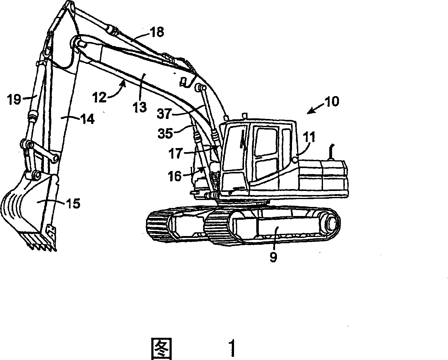
[0023] Although the invention is described in the context of its use in an excavator, it may also be implemented on other types of hydraulically operated equipment.

[0024] Referring first to FIG. 1 , an excavator 10 is composed of a cab 11 and a bracket assembly 12 , wherein the cab 11 is supported by crawlers, and the bracket assembly 12 is connected to the cab for up and down movement. The frame assembly 12 is subdivided into a frame 13, an arm 14 and a bucket 15 which are pivotally connected to each other. The bracket 13 is connected with the cab 11 and can move up and down around a pivot driven by a pair of hydraulic cylinder assemblies 16 and 17, wherein the hydraulic cylinder assemblies 16 and 17 are mechanically connected in parallel between the cab and the bracket. On a typical excavator, the hydraulic cylinders of assemblies 16 and 17 are connected to the cab 11 and the piston rod is connected to the bracket 13 so that the force of gravity on the bracket tends to re...


PUM


Abstract

The present invention relates to energy recovery and reuse technology for hydraulic systems, in particular to a hydraulic system having a valve assembly with two working ports connected to chambers of first and second hydraulic cylinders, the valve assembly having First and second hydraulic cylinders are mechanically connected to the machine part in parallel. The separation control valve is connected between the first chambers of the two hydraulic cylinders, and the branch control valve is connected between the working chambers. A recovery control valve connects the reservoir to the first chamber of the second hydraulic cylinder. Opening and closing the valves in various combinations allows fluid to flow from one or both hydraulic cylinders to a reservoir where the fluid is stored under pressure, and the stored fluid is then used to drive one or both hydraulic cylinders. A shunt control valve is used to direct fluid drained from one chamber of each hydraulic cylinder to the other chamber of those hydraulic cylinders. Therefore, hydraulic systems recover and reuse energy in various ways.

Description

[0001] Cross References to Related Applications [0002] This application claims priority to US Provisional Patent Application No. 60 / 865710, filed November 14, 2006, and US Provisional Patent Application No. 60 / 913,457, filed April 23, 2007. [0003] Statement Regarding Federally Sponsored Research or Development [0004] Not applicable technical field [0005] The present invention relates to a hydraulic system for controlling the flow of fluid to a hydraulic actuator that moves mechanical components on a machine, and more particularly to recovering energy from the hydraulic actuator and subsequently using the recovered energy to Hydraulic actuators provide power. Background technique [0006] Construction and agricultural equipment utilize hydraulic systems to operate various mechanical components. For example, an excavator is a common type of construction machine that has a frame that is pivotally connected to a tractor at one end and h...

Claims


Application Information

Patent Timeline
IPC IPC(8): F15B21/14F15B15/02F15B15/20
Inventor D·B·史蒂芬森K·A·塔伯E·P·哈姆金斯J·L·普法弗
Owner HUSCO INT INC
Why Eureka
Try Eureka