Electric valve

A technology of electric valves and valve shafts, which is applied in the direction of lifting valves, valve devices, valve details, etc., can solve the problems of high-priced stepping motors, large total frictional resistance, and large power consumption, and achieve device cost suppression, reduced frictional resistance, and The effect of reducing the number of parts

Active Publication Date: 2008-07-16
FUJIKOKI MFG CO LTD
View PDF2 Cites 12 Cited by
  • Summary
  • Abstract
  • Description
  • Claims
  • Application Information

AI Technical Summary

Problems solved by technology

[0021] However, in the electric valve 10', there is a problem that a large and expensive stepping motor with a large output torque must be used because a large frictional resistance is generated when the valve is opened which requires the maximum driving torque. And it consumes a lot of power
[0044] In other words, in the conventional electric valve 10', there is the following problem: when opening the valve that requires the maximum driving torque, there are two places where frictional resistance occurs (the lower surface of the top 32a of the valve shaft frame 32 and the lower surface of the spring support member 39). The frictional resistance between Tb+the frictional resistance Tc between the upper surface of the top 32a of the valve shaft frame 32 and the lower end of the push nut 33), the total frictional resistance is relatively large, so it is necessary to use a large and expensive stepper with a large output torque. electric motor, and consumes a lot of power

Method used


Image

  • Electric valve
  • Electric valve
  • Electric valve

Examples


Embodiment Construction

[0078] Next, a first embodiment of the electric valve according to the present invention will be described with reference to the drawings.

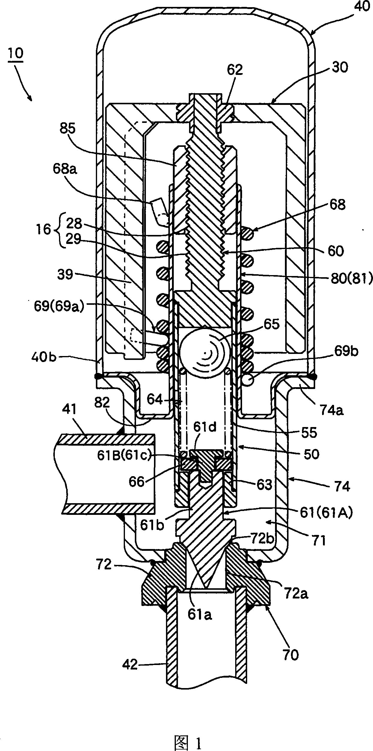
[0079] Fig. 1 shows a first embodiment of an electric valve of the present invention.

[0080] The electric valve 10 shown in FIG. 1 has a valve body 70 having a valve chamber 71 . The valve body 70 includes: a valve seat member 72 having a circular valve port 72a and a conical valve seat 72b; and a cylindrical valve with a container receiving ring shoulder 74a made by stamping. In the chamber forming member 74, the flow rate of fluid such as refrigerant is adjusted by the valve body 61 that is in contact with and separated from the valve seat 72b. The bottom surface portion with the window hole of the valve chamber forming member 74 is fixed to the valve seat member 72 by press fitting, welding, or the like. In addition, the lower end portion 40b of the bottomed cylindrical container 40 which opens downward is hermetically joined to th...


PUM


Abstract

The invention provides an electro valve of which the valve core comprises: a basal body which is fixed with a taper valve part, a major diameter shaft part, a minor diameter shaft part and a flange part located on a valve seat in turns from the lower; and a collar hanger component whcih is lagged on the minor diameter shaft part of the basal body in a relative move and rotation state in an axial direction, and stopped by a tubby stop part fixed on a valve support to support the lower end of a helical compression spring. When the valve support is located in a lowest position, the undersurface of the collar hanger component is press bonded on a step surface at upper of the major diameter shaft part of the basal body, while a defined gap is formed beteen the undersuface of the collar hanger component and the upper surface of the stop part. When the rotor and the valve support rotates a defined amount from the lowest position, the upper surface of the tubby stop part abuts on the undersurface of the collar hanger component, and the collar hanger component aparts from the upper step surface of the major diameter shaft part; and when the rotor and the valve support further rotates, the collar hanger component pushes the flange part up. The invention can redece the frictional resistance of the structural member, reduce the drive torque needed for opening the valve, obtain a simple structure with a fewer components, and reduce the cost of the device.

Description

technical field [0001] The present invention relates to electric valves, in particular to stepping motor-driven electric valves used as flow control valves in refrigeration circuits such as air conditioners and refrigerators. Background technique [0002] The inventors of the present application have devised an electric valve as shown in FIG. 10 as an electric valve to be incorporated into an air conditioner, a refrigerator, and the like. [0003] The electric valve 10' shown in FIG. 10 has a valve body 70 having a valve chamber 71. As shown in FIG. The valve body 70 includes a valve seat member 72 and a valve chamber forming member 74. The valve seat member 72 has a valve port 72a with a circular cross section and a conical valve seat 72b. The cylindrical shape of the portion 74a, on the container receiving ring shoulder portion 74a of the valve chamber forming member 74, the lower end portion 40b of the bottomed cylindrical container 40 with a lower opening is hermeticall...

Claims


Application Information

Patent Timeline
Patent Type & Authority Applications(China)
IPC IPC(8): F16K31/04F16K1/38F25B41/04
Inventor 原田贵雄菅沼威
Owner FUJIKOKI MFG CO LTD
Why Eureka
Try Eureka