

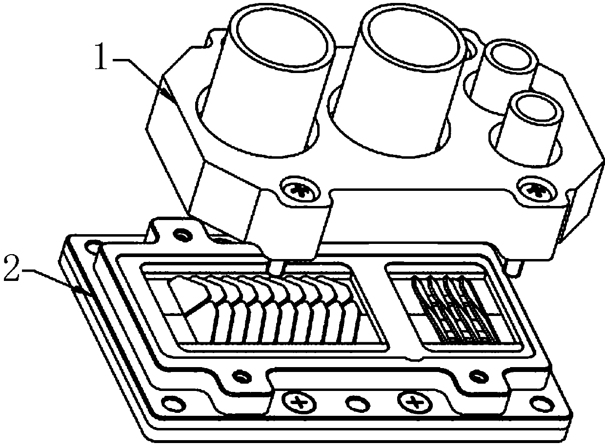
Electric connector and electric connector assembly
A technology for electrical connectors and contacts, which is applied to the parts, connections, and contact parts of the connecting device, can solve the problems of the increase in the size of the elastic parts, the laborious insertion process, and the increase in the required space, and achieve reliable connection. and separation, insertion, easy, compact effect
- Summary
- Abstract
- Description
- Claims
- Application Information
AI Technical Summary
Problems solved by technology
Method used
Image

Examples
Embodiment 2
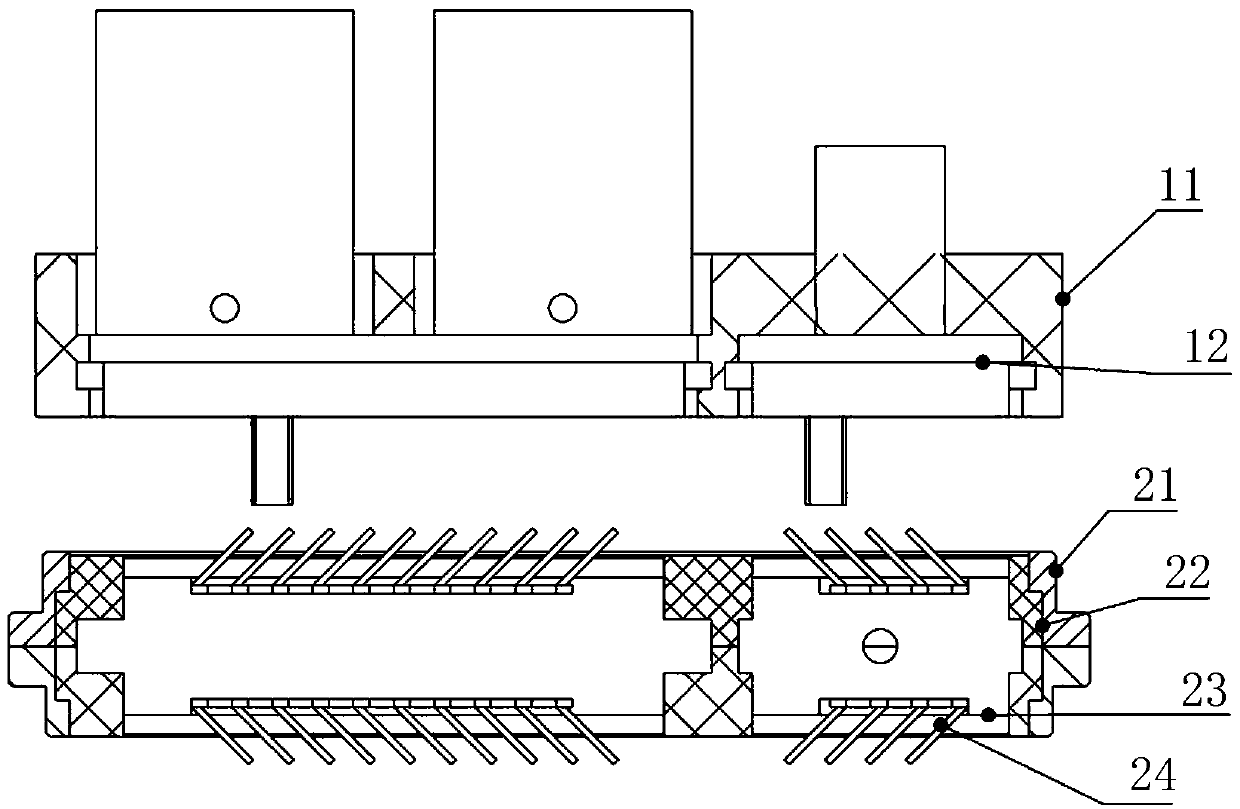
[0045] Embodiment 2: as Figure 4 As shown, the difference from Embodiment 1 is that the conductive member 12 is an arc-shaped plate, and the protruding lengths of the overhanging ends of the conductive reeds 24 are different. The shape is adapted to the arc curve, so that the distance between each conductive reed 24 and the conductive member 12 is consistent.
Embodiment 3
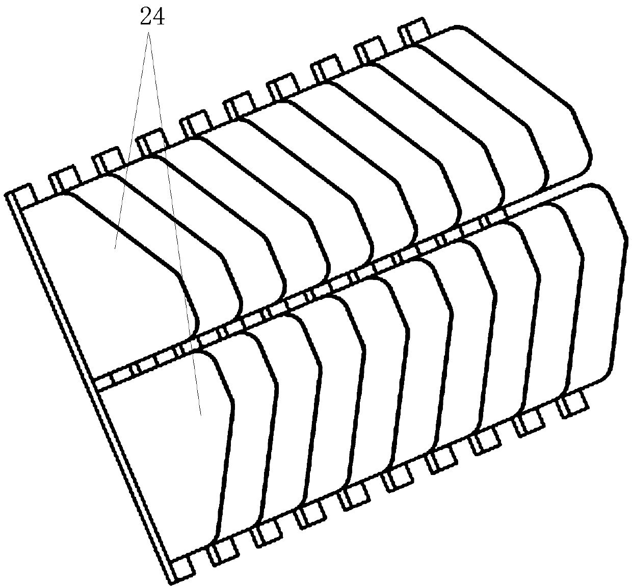
[0046] Embodiment 3: as Figure 5 As shown, the difference from Embodiment 1 is that the inclination direction of each conductive reed 24 in the same conductive contact area can be different, and the inclination direction of this embodiment is opposite to make the conductive reed 24 symmetrical.
Embodiment 4
[0047] Embodiment 4: as Figure 6 As shown, the difference from Embodiment 1 is that the conductive reed 24 is not limited to a straight shape, and can also be replaced by a reed of various shapes such as an arc-shaped piece, but the deformation direction of the reed should be roughly along the direction of the insertion direction.
PUM
 Abstract
Description
Claims
Application Information