Dynamic touching moire compensation process and related LCD system

A compensation method and touch technology, applied in the direction of static indicators, instruments, etc., can solve the problems of irregular display of the LCD screen, uncomfortable visual experience, short duration of moiré effect, etc.

Inactive Publication Date: 2008-07-16
AU OPTRONICS CORP
View PDF0 Cites 13 Cited by
  • Summary
  • Abstract
  • Description
  • Claims
  • Application Information

AI Technical Summary

Problems solved by technology

Usually, the moiré effect will cause the irregular display of the LCD screen area, resulting i

Method used


Image

  • Dynamic touching moire compensation process and related LCD system
  • Dynamic touching moire compensation process and related LCD system
  • Dynamic touching moire compensation process and related LCD system

Examples


Embodiment Construction

[0042] In order to make the present invention more obvious and easy to understand, the dynamic touch moiré compensation method and the related liquid crystal display system according to the present invention will be described in detail below with specific examples in conjunction with the attached drawings, but the provided examples are not intended to The scope covered by the present invention is limited, and the step numbers of the method flow are not used to limit the order of execution. Any method with the same effect produced by the recombined execution flow of the method steps is covered by the present invention.

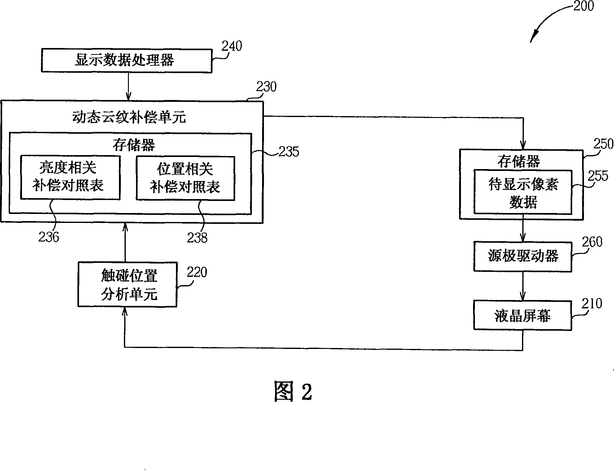
[0043] Please refer to FIG. 2 . FIG. 2 is a schematic block diagram of an embodiment of a liquid crystal display system with dynamic touch moiré compensation according to the present invention. The liquid crystal display system 200 includes a liquid crystal screen 210 , a touch position analysis unit 220 , a dynamic moiré compensation unit 230 , a display data p...


PUM


Abstract

The invention provides a dynamic touching MURA compensation method and an LCD system thereof; the method comprises that: a touching position signal is generated according to a touching position of a touching event of an LCD screen; a signal compensation process of a pixel brightness signal relative to the touching position of an original pixel data is executed according to the touching position, thereby generating a pixel data to be displayed; and the pixel data to be displayed is displayed on the LCD screen. Moreover, the invention discloses an LCD system provided with dynamic touching MURA compensation, which comprises an LCD screen, a touching signal analyzing module, a display data processor, a dynamic MURA compensation unit and a source electrode driver.

Description

technical field [0001] The present invention relates to a display data compensation method and a related liquid crystal display system, in particular to a dynamic data compensation method for touch moiré (MURA) and a related liquid crystal display system. Background technique [0002] Liquid crystal display (liquid crystal display, LCD) is currently the most widely used type of flat panel display, which has the characteristics of light and thin appearance, power saving and no radiation pollution. The working principle of the liquid crystal display device is to change the arrangement state of the liquid crystal molecules in the liquid crystal layer by changing the voltage difference between the two ends of the liquid crystal layer, thereby changing the light transmittance of the liquid crystal layer to display different images. In various electronic products including liquid crystal display devices, such as multimedia players, mobile phones or personal digital assistants (PDA...

Claims


Application Information

Patent Timeline
IPC IPC(8): G09G3/36G02F1/133
Inventor 廖士颐郑国兴谢曜任周恒生张孟祥
Owner AU OPTRONICS CORP
Why Eureka
Try Eureka