Differential limiting control device of four-wheel drive vehicle

A technology of control device and wheel drive, which is applied in the direction of control device, safety device of power plant control mechanism, vehicle components, etc., which can solve the problems of reduced turning performance, increased differential limiting force between front and rear wheels, and hindering the turning action of the vehicle. Achieve the effects of improved turning performance, good turning performance, and proper differential limitation

Active Publication Date: 2008-07-16
MITSUBISHI MOTORS CORP
View PDF1 Cites 11 Cited by
  • Summary
  • Abstract
  • Description
  • Claims
  • Application Information

AI Technical Summary

Problems solved by technology

Therefore, as a result, the differential restriction between the front and rear wheels acts in the direction of promoting understeer, hindering the turning behavior of the vehicle, and there is a problem that the turning performance of the vehicle is reduced.
Furthermore, in the technology described in the above-mentioned Patent Document 1, the differential limiting force between the front and rear wheels is increased to suppress slippage, so the increase of the running limiting force strengthens the understeer and becomes the main cause of the deterioration of the cornering performance. Complete measures to eliminate the above problems

Method used


Image

  • Differential limiting control device of four-wheel drive vehicle
  • Differential limiting control device of four-wheel drive vehicle
  • Differential limiting control device of four-wheel drive vehicle

Examples


Embodiment Construction

[0020] Next, an embodiment of the present invention implemented in a differential limit control device for an electronically controlled on-demand 4-wheel drive vehicle based on an FF vehicle will be described.

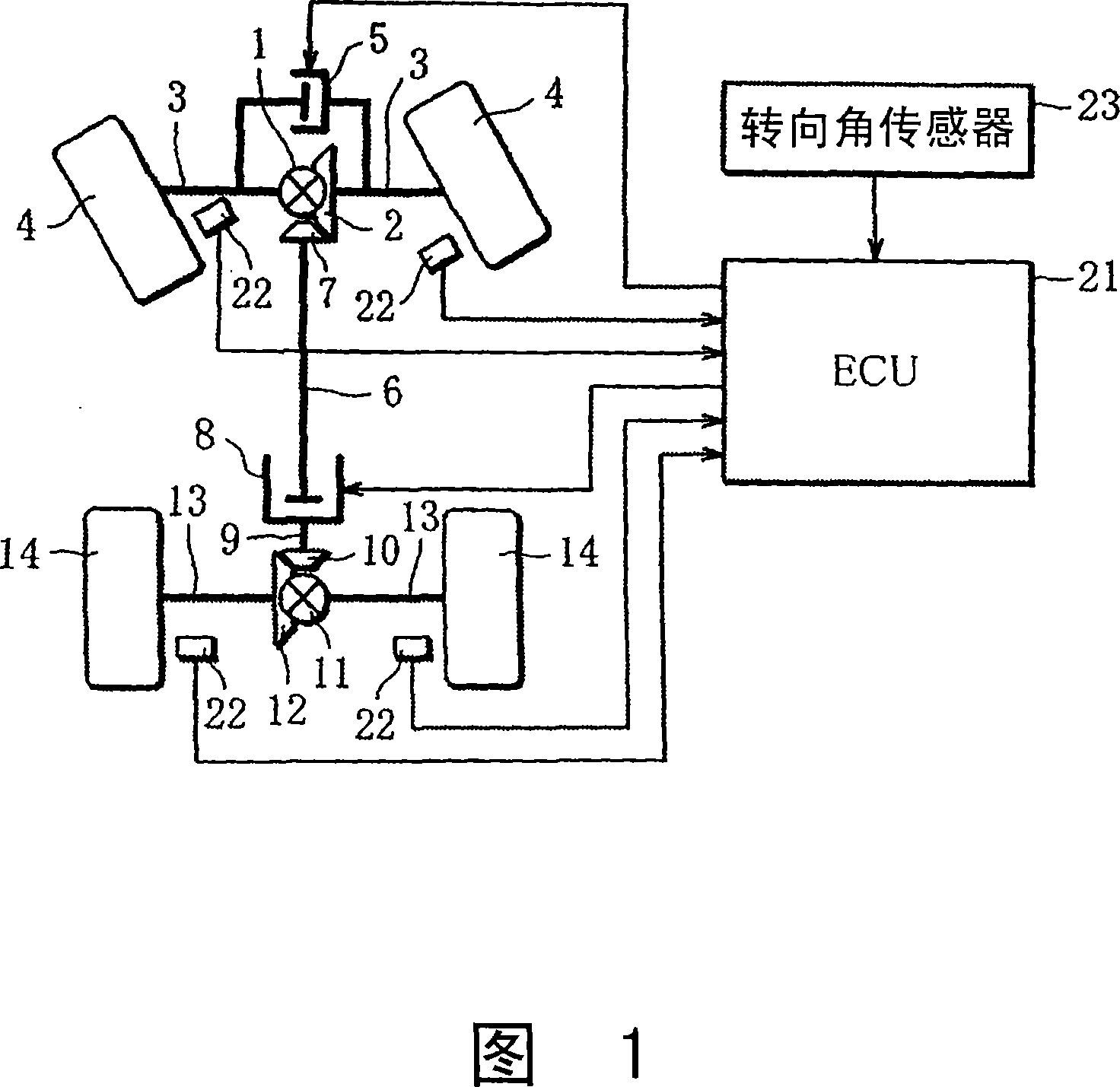
[0021] FIG. 1 is an overall configuration diagram showing a differential limit control device for a four-wheel drive vehicle according to the present embodiment. A front differential 1 is provided between the left and right wheels on the front wheel side, and the power of an unillustrated engine is input to an internal gear 2 fixed to the front differential 1 via an unillustrated transmission. On the front differential 1, the left and right front wheels 4 are connected through the drive shaft 3, so that the front differential 1 transmits the power of the engine input to the internal gear 2 to the left and right front wheels 4, making it differential verb: move. An electronically controlled front limited-slip differential 5 (left and right wheel differential limiting d...


PUM


Abstract

A differential limiting control device of a four-wheel drive vehicle, wherein the restraint torque TF of an electronically controlled front limited slip differential (5) between front right and front left wheels is controlled based on a right and left wheel rotational speed difference Delta NF for control as a rotational speed difference between the front right and front left side wheels. Furthermore, the restraint torque TC of an electronically controlled coupling (8) between the front and rear wheels is controlled based on a front and rear wheel rotational speed difference Delta NC for control provided by deducting 1 / 2 (|Delta NF| / 2) of the rotational speed difference between the right and left wheels from a rotational speed difference (Delta NCT - Delta NCD) between the front and rear wheels.

Description

technical field [0001] The present invention relates to a differential limiting control device for controlling the differential limiting force between the left and right wheels and between the front and rear wheels of a four-wheel drive vehicle. Background technique [0002] As a 4-wheel drive vehicle, there are known drive-on-demand 4-wheel drive vehicles that transmit the power of the engine often to one of the front wheels or the rear wheels and transmit part of the power to the other side of the front wheels or the rear wheels as needed, or often to the rear wheels. A full transmission 4-wheel drive vehicle that transmits driving force to 4 wheels. In these 4-wheel drive vehicles, some electronically controlled differential limiting devices are installed between the left and right wheels or between the front and rear wheels, so that the difference between the left and right wheels or the front and rear wheels can be adjusted according to the driving state of the vehicle,...

Claims


Application Information

Patent Timeline
Patent Type & Authority Applications(China)
IPC IPC(8): B60K17/35B60K17/348
CPCB60W2520/28B60W2520/10B60W10/119B60W30/045B60W2520/263B60W10/16B60W10/02B60K28/165B60W2540/18
Inventor 后田祐一泽濑熏藤井祐介
Owner MITSUBISHI MOTORS CORP
Why Eureka
Try Eureka