Drive force transmission apparatus, control method of drive force transmission apparatus, and limited slip differential

a transmission apparatus and control method technology, applied in the direction of underwater vessels, special data processing applications, non-deflectable wheel steering, etc., can solve the problem that the wheel speed sensors cannot accurately detect the rotational speed of the corresponding wheels, the rotation difference between the front wheels and the rear wheels cannot be absorbed, and the tight cornering phenomenon. achieve the effect of improving the traction performance of the vehicle and low friction coefficien

Active Publication Date: 2009-10-01
JTEKT CORP
View PDF11 Cites 15 Cited by
  • Summary
  • Abstract
  • Description
  • Claims
  • Application Information

AI Technical Summary

Benefits of technology

[0009]Accordingly, it is an objective of the present invention to provide a drive force transmission apparatus, a control method of the drive force transmission apparatus, and a limited slip differential that are capable of improving the traction performance of a vehicle on a road surface with a low friction coefficient while suppressing a tight corner braking phenomenon caused by steering the steering wheel when the speed of the vehicle is smaller than or equal to a speed corresponding to a starting state of the vehicle.

Problems solved by technology

Accordingly, if the torque transmission capacity is set to a great value when the four-wheel-drive vehicle including the aforementioned drive force transmission apparatus turns at a small turning radius, the rotation difference between the front wheels and the rear wheels cannot be absorbed.
This possibly leads to the tight corner braking phenomenon.
For example, if the vehicle speed is lower than the upper limit value of the vehicle speed range corresponding to the starting state of the vehicle, the wheel speed sensors may not be capable of accurately detecting the rotational speeds of the corresponding wheels.
If, in this case, the steering wheel is steered in such a manner that the turning radius of the vehicle becomes smaller than or equal to the aforementioned maximum radius, the above-described disadvantage can occur.
However, if the vehicle is started on a road surface with a low friction coefficient such as an icy road surface and the torque transmission capacity is reduced based on the steering wheel turning angle, as has been described, sufficient torque may not be transmitted to the auxiliary drive wheels despite the fact that the vehicle is skidding.
This lowers the traction performance of the vehicle.
These problems occur not only with a drive force transmission apparatus having a torque coupling, but also with a torque distribution mechanism that distributes torque of a drive source to front wheels and rear wheels, and with a limited slip differential having a differential limiting mechanism capable of limiting differential motion between a first driveshaft connected to the front wheels and a second driveshaft connected to the rear wheels.

Method used


Image

  • Drive force transmission apparatus, control method of drive force transmission apparatus, and limited slip differential
  • Drive force transmission apparatus, control method of drive force transmission apparatus, and limited slip differential
  • Drive force transmission apparatus, control method of drive force transmission apparatus, and limited slip differential

Examples


first embodiment

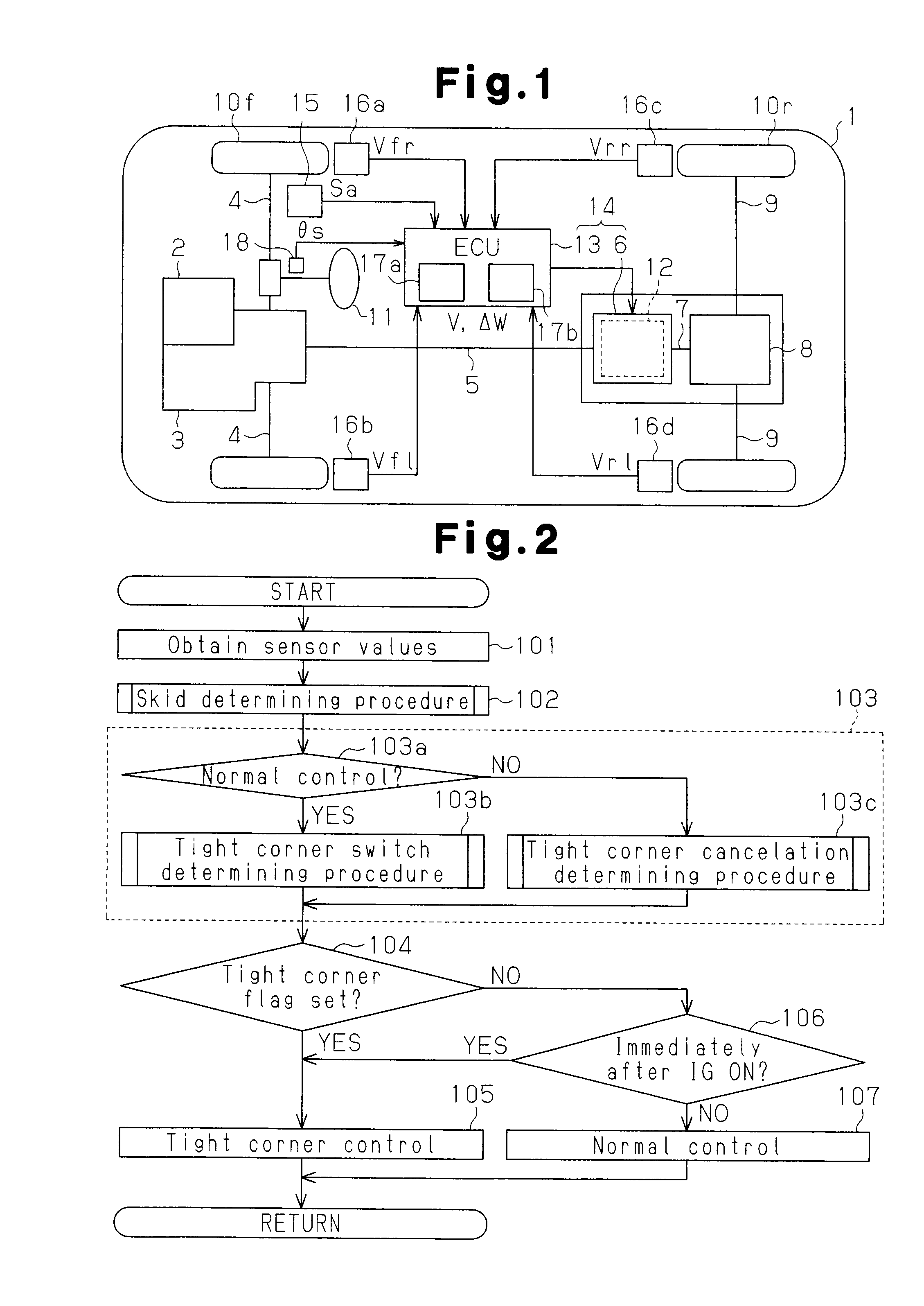
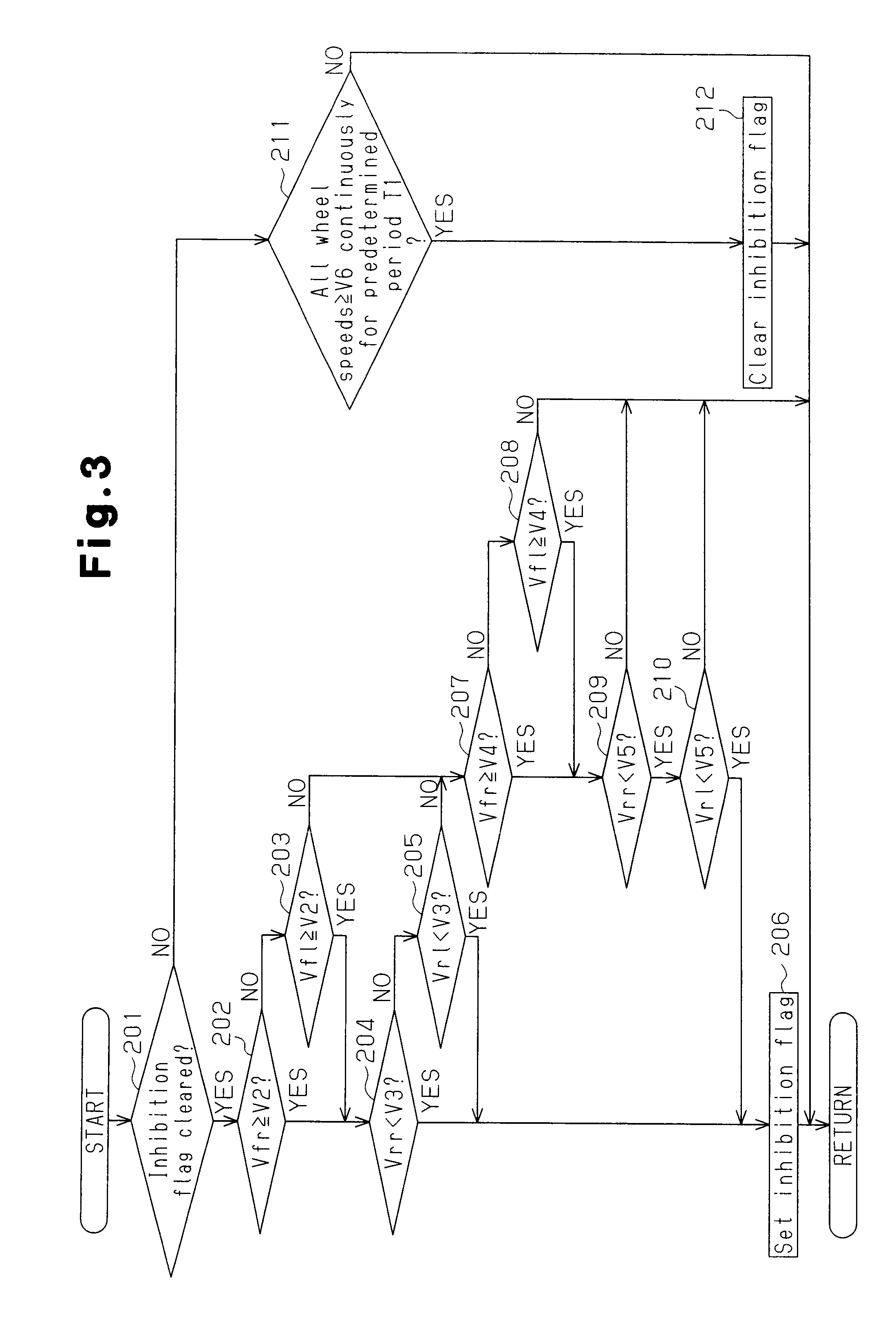
[0022]A first embodiment of the present invention will now be described with reference to FIGS. 1 to 6.

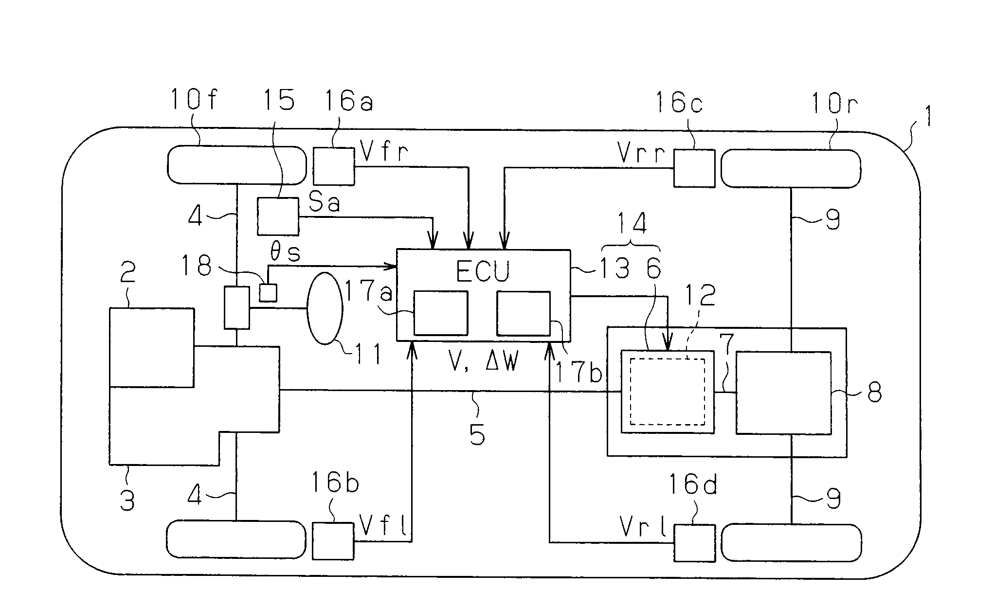
[0023]As illustrated in FIG. 1, a vehicle 1 is a front wheel drive-based four-wheel-drive vehicle. An engine 2 functioning as a drive source is mounted in a front portion (in a left side as viewed in FIG. 1) of the vehicle 1. A transaxle 3 is incorporated in the engine 2. A pair of front axles 4 and a propeller shaft 5 are connected to the transaxle 3. A pair of front wheels 10f are provided for the corresponding front axles 4.

[0024]The propeller shaft 5 is connectable to a drive pinion shaft (hereinafter, referred to as a pinion shaft 7) through a torque coupling 6. The pinion shaft 7 is connected to a pair of rear axles 9 through a rear differential 8. A pair of rear wheels 10r are provided on the corresponding rear axles 9.

[0025]The torque of the engine 2 is transmitted to the transaxle 3, which divides the torque to two paths. Specifically, the torque of the engine 2 is transmi...

second embodiment

[0104]A second embodiment of the present invention will now be described with reference to FIG. 7.

[0105]For the illustrative purposes, same or like reference numerals are given to components in FIG. 7 that are the same as or like corresponding components of the first embodiment and explanation of these components is omitted.

[0106]As illustrated in FIG. 7, a transmission 21 is incorporated in the engine 2. A transfer 23 is connected to the transmission 21 through an input shaft 22. A first propeller shaft 24 functioning as a first driveshaft and a second propeller shaft 25 functioning as a second driveshaft are connected to the transfer 23.

[0107]The first propeller shaft 24 is connected to a pair of front axles 4 through a front differential 26. The second propeller shaft 25 is connected to a pair of rear axles 9 through a rear differential 8. Torque produced by the engine 2 is transmitted from the transmission 21 to the transfer 23 through the input shaft 22. The torque of the engin...


PUM


Abstract

When determining that a vehicle is not skidding, the ECU carries out tight corner control if vehicle speed is smaller than the upper limit value of the vehicle speed range corresponding to the starting state of the vehicle and the steering wheel turning angle of a steering wheel is greater than or equal to the minimum value of the steering wheel turning angle at which the tight corner braking phenomenon may occur. When determining that the vehicle is skidding, the ECU inhibits the tight corner control even if the vehicle speed is smaller than the upper limit value and the steering wheel turning angle is greater than or equal to the minimum value of the steering wheel turning angle at which the tight corner braking phenomenon may occur.

Description

BACKGROUND OF THE INVENTION[0001]The present invention relates to a drive force transmission apparatus including a torque coupling capable of changing the ratio of torque of a drive source distributed to the main drive wheels and the auxiliary drive wheels of a four-wheel-drive vehicle, a control method of the drive force transmission apparatus, a torque distribution mechanism that distributes torque of a drive source to front wheels and rear wheels, and a limited slip differential having a differential limiting mechanism capable of limiting differential motion between the front and rear wheels.[0002]A four-wheel-drive vehicle having main drive wheels and auxiliary drive wheels are known. The main drive wheels constantly receive torque of a drive source, while the auxiliary drive wheels receive the torque when necessary according to the state of the vehicle. A drive force transmission apparatus is provided between the drive source and the auxiliary drive wheels of the four-wheel-dri...

Claims


Application Information

Patent Timeline
Patent Type & Authority Applications(United States)
IPC IPC(8): B60T8/24G06F19/00B60K17/35
CPCB60K23/0808
Inventor SHIGETA, RYOUHEIOHNO, AKIHIROANDO, HIROYUKIMITA, MASAKINOZU, TOMOHIRO
Owner JTEKT CORP
Why Eureka
Try Eureka