Pneumatic tire

a technology of pneumatic tires and grooves, which is applied in the direction of non-skid devices, vehicle components, transportation and packaging, etc., can solve the problems of reducing the ratio of groove area, deteriorating snow traction performance, and reducing snow traction performance on wet road surfaces, so as to improve snow traction performance and enhance snow traction performance , the effect of improving the groove area

Active Publication Date: 2006-06-08
YOKOHAMA RUBBER CO LTD
View PDF8 Cites 11 Cited by
  • Summary
  • Abstract
  • Description
  • Claims
  • Application Information

AI Technical Summary

Benefits of technology

[0006] According to the present invention described above, because there are blocks defined by the transverse grooves between the first main see-through grooves instead of a conventional rib disposed therebetween, the groove area increases, whereby snow traction performance can be enhanced.
[0007] Although a directional tread pattern having rug grooves inclined in the reverse rotational direction of the tire tends to collect water in the center side of the tire during traveling on wet road surfaces, the transverse grooves are arranged so as to be in V shapes having vertexes facing to the reverse rotational direction of the tire, as described above, whereby water removed by the edges of the blocks providing water screen removing effects smoothly flows into the first main see-through grooves through the transverse grooves. Therefore, the ground contact properties of the blocks with wet road surfaces or icy road surfaces can be secured in the center region of the tread surface, whereby braking performance on wet road surfaces can be enhanced, and braking performance on ice that is equal to or more than that of the prior art tire having a center rib can be obtained.

Problems solved by technology

However, Provision of the center rib reduces the ratio of groove area, compared with blocks, whereby a decrease in braking performance on wet road surfaces can not be avoided.
Another problem is that snow traction performance is deteriorated.

Method used


Image

  • Pneumatic tire
  • Pneumatic tire

Examples


example 1

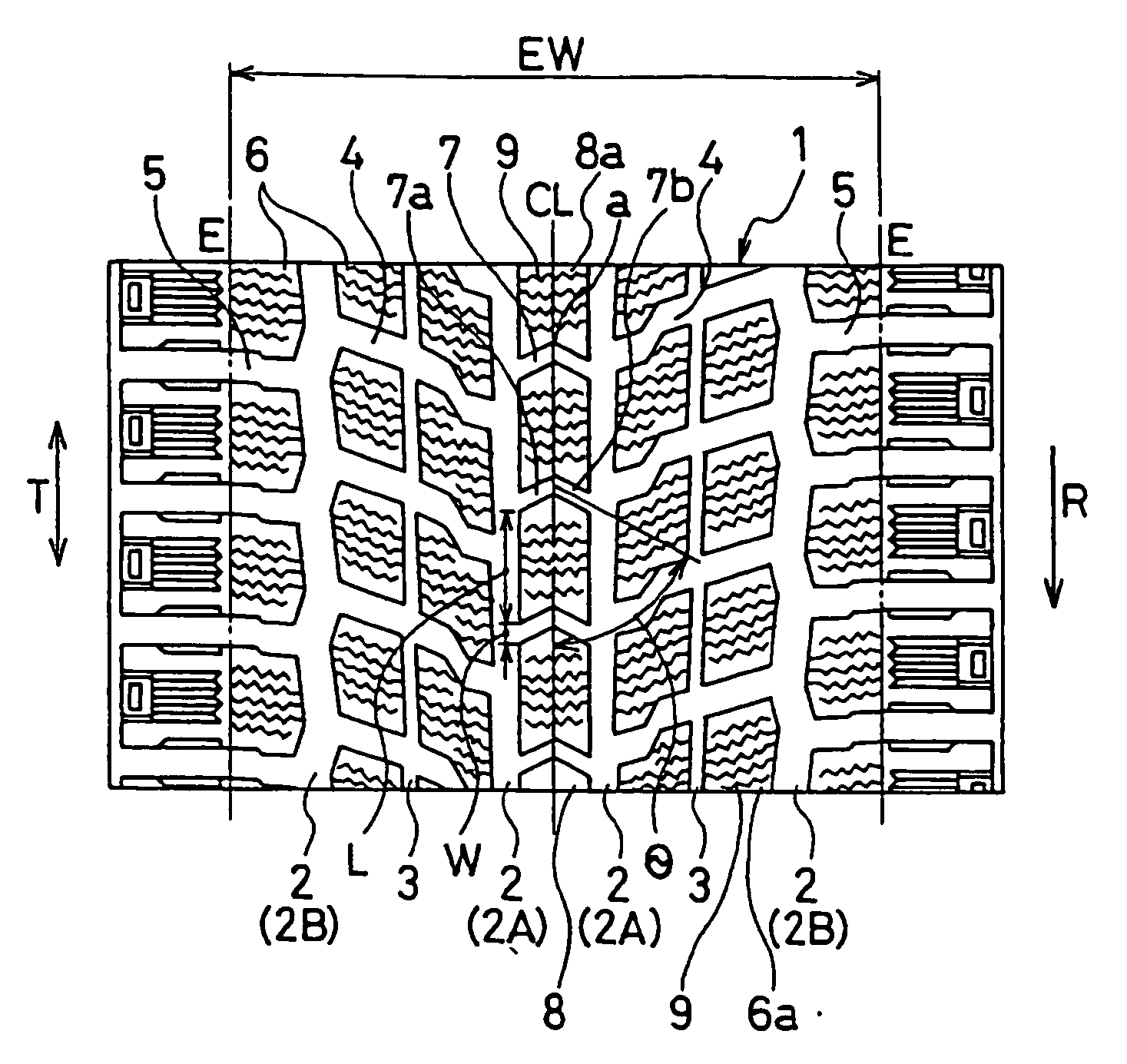
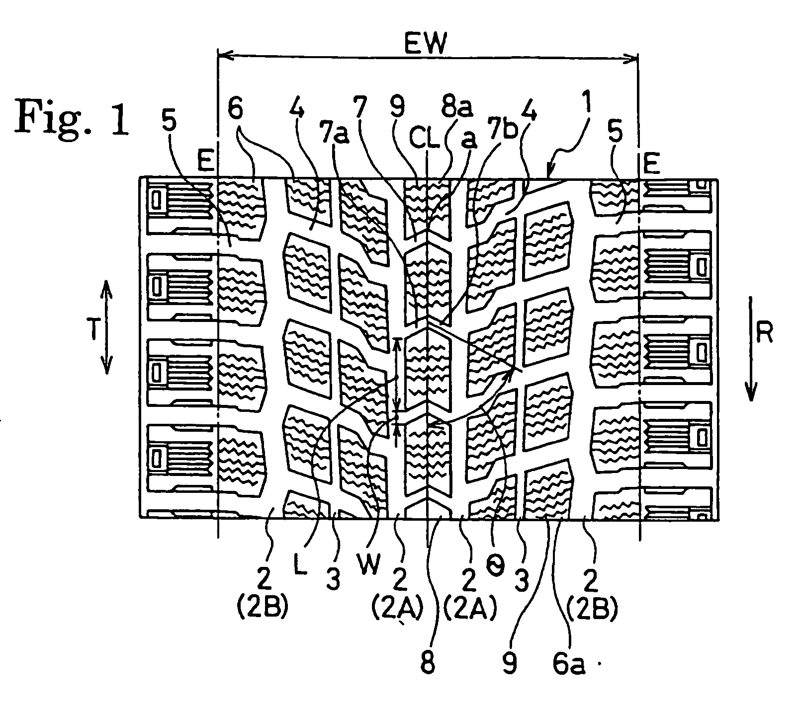
[0030] Prepared were four test tires each according to the present invention tires 1 to 3, comparison tires 1 to 3, and conventional tire 1, having the same tire sizes of 215 / 70R16; the present invention tires 1 to 3 and comparison tires 2 and 3 each had a pattern shown in FIG. 1, in which the groove width W of the V-shaped transverse grooves with vertexes facing to the reverse rotational direction of the tire, the ratio ACA / GCA of the total ground contact area ACA of the blocks to the ground contact area GCA of the entire tread surface, and the position of each first main see-through groove were as shown in Table 1; the comparison tire 1 had the same pattern as the present invention tire 1 except that the vertexes of the transverse grooves faced to the rotational direction of the tire; and the conventional tire 1 had the same pattern as the present invention tire 1 except that there was a rib between the first main see-through grooves.

[0031] The inclination angle θ of each groove ...

example 2

[0040] Prepared were four test tires each according to the present invention tires 4 to 6 and comparison tires 4 and 5, having the same tire sizes as in EXAMPLE 1; the present invention tires 4 to 6 and comparison tires 4 and 5 each had a pattern shown in FIG. 1, in which the groove width W of the V-shaped transverse grooves with vertexes facing to the reverse rotational direction of the tire, the ratio ACA / GCA of the total ground contact area ACA of the blocks to the ground contact area GCA of the entire tread surface, and the position of each first main see-through groove were as shown in Table 2.

[0041] The inclination angle θ of each groove portion of each test tire was 70 degrees, and the second main see-through grooves were located at the positions of 40% of the tire ground contact width EW.

[0042] Evaluation testing for wet braking performance, snow traction performance and ice braking performance was carried out on the test tires as in EXAMPLE 1, obtaining the results shown ...

example 3

[0044] Prepared were four test tires each according to the present invention tires 7 to 9 and comparison tires 6 and 7, having the same tire sizes as in EXAMPLE 1; the present invention tires 7 to 9 and comparison tires 6 and 7 each had a pattern shown in FIG. 1, in which the groove width W of the V-shaped transverse grooves with vertexes facing to the reverse rotational direction of the tire, the ratio ACA / GCA of the total ground contact area ACA of the blocks to the ground contact area GCA of the entire tread surface, and the position of each first main see-through groove were as shown in Table 3.

[0045] The inclination angle θ of each groove portion of each test tire was 70 degrees, and the second main see-through grooves were located at the positions of 40% of the tire ground contact width EW.

[0046] Evaluation testing for wet braking performance, snow traction performance and ice braking performance was carried out on the test tires as in EXAMPLE 1, obtaining the results shown ...


PUM


Abstract

A tread surface the tire rotational direction of which is specified in one direction includes a first main see-through groove extending in the circumferential direction of the tire in a region of from 4% to 15% of the tire ground contact width from the tire equatorial plane toward each of left and right sides. Rug grooves obliquely extend from the first main see-through grooves toward the outer sides of the tire in the reverse rotational direction of the tire so as to communicate with the tire ground contact ends, the rug grooves being disposed at prescribed intervals in the circumferential direction of the tire. Blocks are defined by the rug grooves and the first main see-through grooves. V-shaped transverse grooves are disposed between the first main see-through grooves at prescribed intervals in the circumferential direction of the tire, the transverse grooves having vertexes that face to the reverse rotational direction of the tire. Blocks are defined by the transverse grooves and the first main see-through grooves. The groove width W of each transverse groove measured in the circumferential direction of the tire is ranged from 0.1 L to 0.25 L with respect to the tire circumferential length L of the block adjacent the transverse groove. The ratio ACA/GCA of the total ground contact area ACA of the blocks to the ground contact area GCA of the entire tread surface is in the range of 55% to 75%.

Description

TECHNICAL FIELD [0001] The present invention relates to pneumatic tires adapted for icy and snowy roads, and more particularly, to a pneumatic tire which can improve braking performance on wet road surfaces and traction performance on snow while ensuring performance on ice. TECHNICAL BACKGROUND [0002] Conventionally, there is well-known a pneumatic tire for icy and snowy roads having a directional tread pattern including V-shaped grooves disposed therein, in which a center rib is provided on the equatorial plane of the tire in the tread surface to enhance ice performance (see Unexamined Japanese Patent Application Publication No. 2000-255217, for example). Since the center rib increases the ground contact area, ground contact properties with respect to icy road surfaces increase to enhance performance on ice. [0003] However, Provision of the center rib reduces the ratio of groove area, compared with blocks, whereby a decrease in braking performance on wet road surfaces can not be av...

Claims


Application Information

Patent Timeline
Patent Type & Authority Applications(United States)
IPC IPC(8): B60C11/11B60C11/03B60C11/12
CPCB60C11/01B60C11/0302B60C11/11B60C11/12B60C11/033B60C2011/1213Y10S152/03
Inventor EBIKO, MASAHIRO
Owner YOKOHAMA RUBBER CO LTD
Why Eureka
Try Eureka