Limited slip differential

a differential and slip technology, applied in the field of differentials, can solve the problems of difficult to make a compact unit, heavy differential, and high manufacturing cost, and achieve the effect of reducing material usage, assembly time and manufacturing cos

Inactive Publication Date: 2005-02-01
FORD GLOBAL TECH LLC
View PDF20 Cites 15 Cited by
  • Summary
  • Abstract
  • Description
  • Claims
  • Application Information

AI Technical Summary

Benefits of technology

The above differential allows for a more compact and lightweight differential by removing the differential case and instead engaging

Problems solved by technology

One problem with the above system is that it is difficult to make a compact unit.
Another problem is that these differentials are heavy and it is desirable to reduce their weight to improve fuel economy.
Yet another problem with traditional limited slip differentials is that they are

Method used


Image

  • Limited slip differential
  • Limited slip differential
  • Limited slip differential

Examples


Embodiment Construction

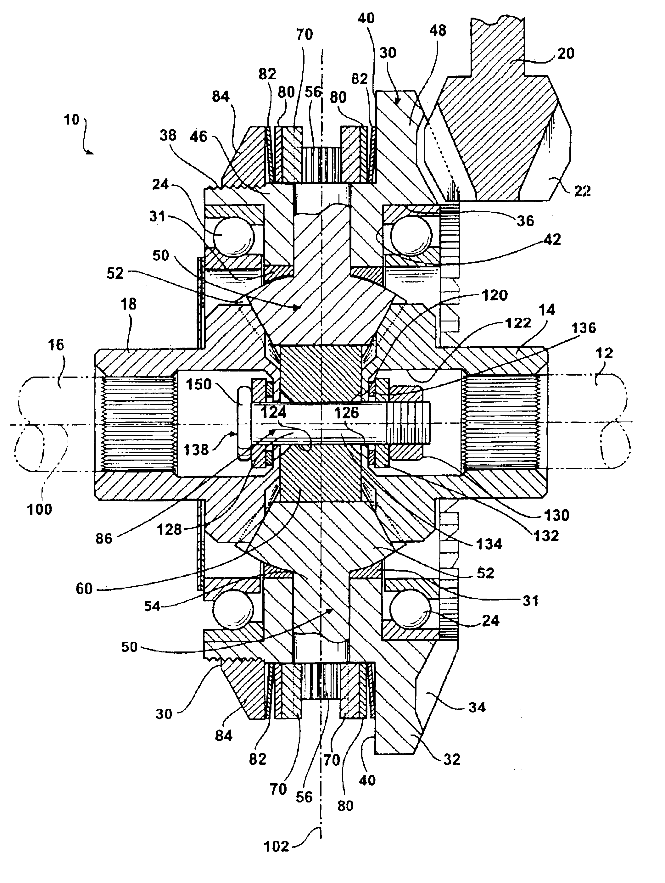
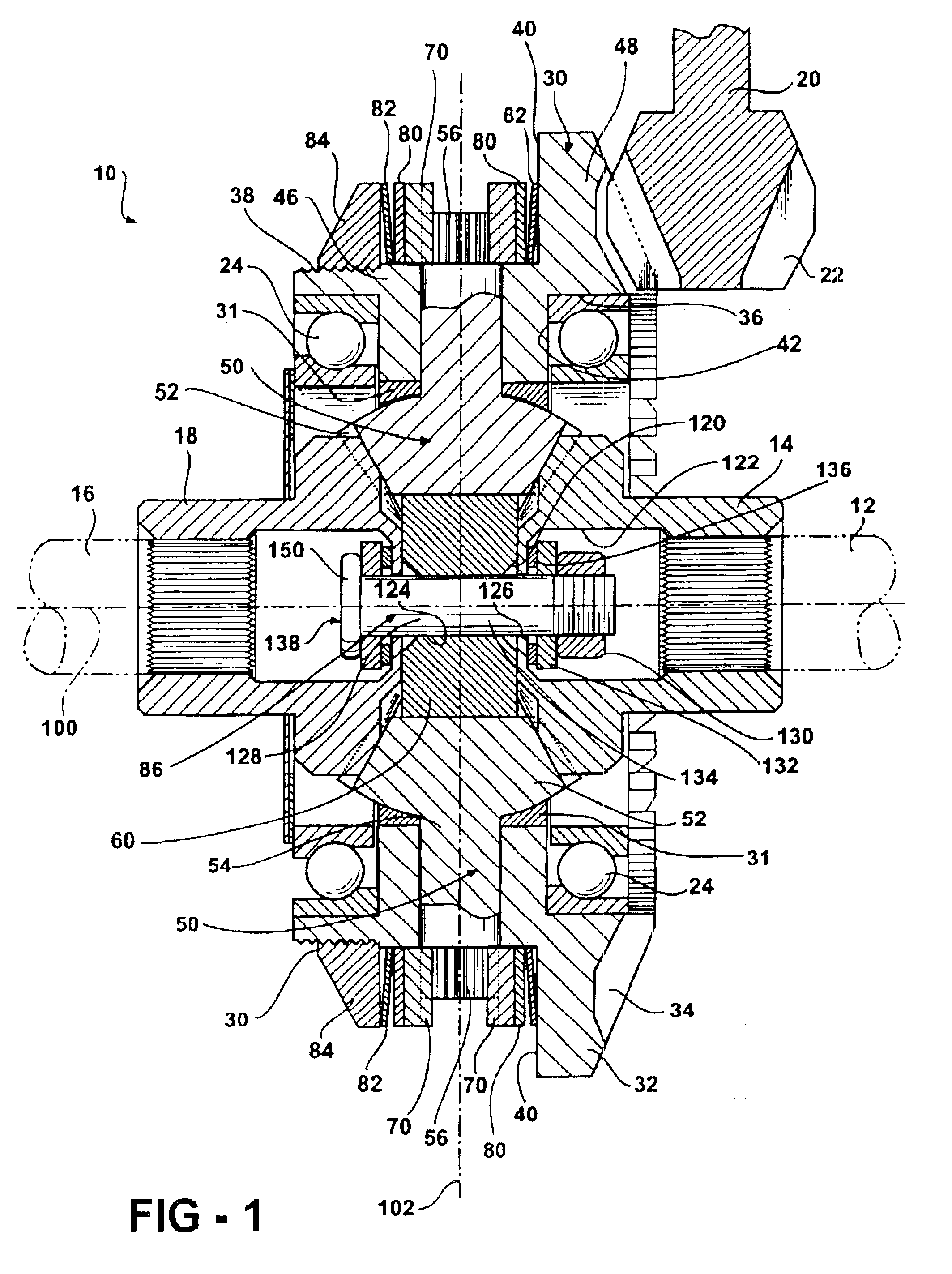
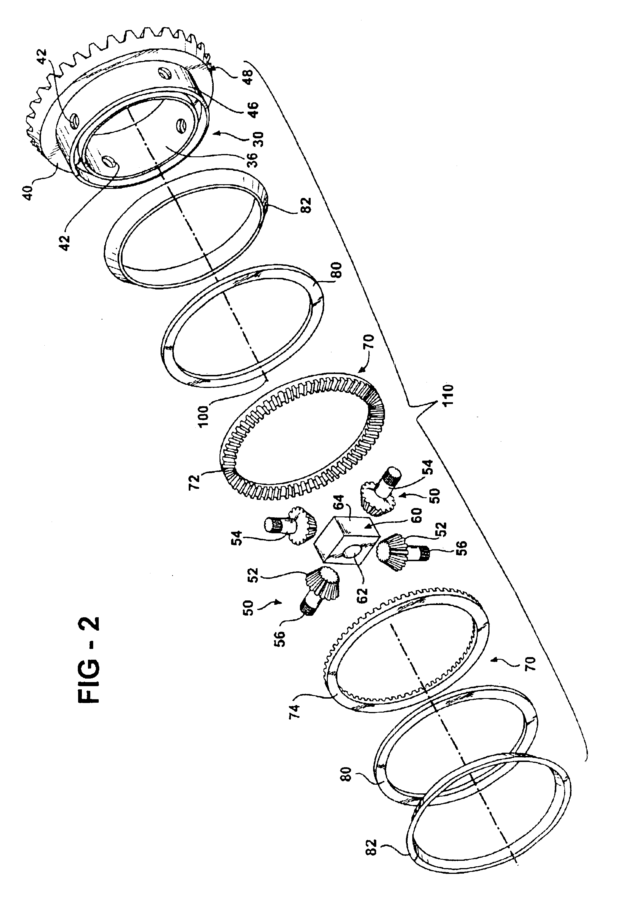
A differential 10 constructed in accordance with the illustrated embodiment is shown in FIG. 1. The differential 10 is illustrated in all figures as being assembled into an independent axle configuration, but it should be readily apparent to one skilled in the art that the differential 10 may be used in other configurations, such as a tubular or beam axle. The differential 10 receives an input torque from a drive shaft 20, and transfers the input torque to a first axle shaft 12 and a second axle shaft 16. More specifically, the drive shaft 20 engages the ring gear 30 and rotates the ring gear 30 about a longitudinal axis 100. The differential case typically found in differentials is eliminated. Instead, the ring gear 30 encases and locates the pinions 50 as well as the first side gear 14 and second side gear 18. A fastener assembly 86 retains and secures the side gears 14 and 18 and pinions 50 within the ring gear 30. The elimination of the traditional differential case allows for a...


PUM


Abstract

A lightweight limited slip differential for a tubular or independent axle assembly. The differential biases the torque applied to the wheels through clutch rings engaged on the pinions. The pinions include a mating surface that engage a similar profile on the clutch rings. The clutch rings may be frictionally restrained or coupled together so that the pinion movement is restrained to bias the torque between the wheels.

Description

BACKGROUND OF THE INVENTIONThe present invention is generally directed to a differential and, more particularly, to a limited slip differential that is compact and lightweight.Limited slip differential gears are commonly found in the auto industry to allow more torque to be transferred to a non-slipping wheel. A driving force is applied to a ring gear attached to the differential case so that the entire differential case is rotated by the driving force. A pair of pinion gears inside the gear case mesh with side gears attached to the wheel axles and allow the wheels to rotate at different speeds while the vehicle is turning or when the wheels are on different surfaces and one wheel is slipping. Typically, multiple disk clutches are interposed between the gear case and the side gears while a spring assembly pushes the side gears and clutches together. The clutches bias the torque, making the wheels spin at the same speed until the wheels overcome this torque bias, such as when a vehic...

Claims


Application Information

Patent Timeline
IPC IPC(8): F16H48/00F16H48/08F16H48/22F16H48/06F16H48/10F16H48/20F16H48/24F16H48/38F16H48/40
CPCF16H48/08F16H48/10F16H48/22F16H48/24F16H2048/405F16H2048/082F16H2048/085F16H2048/201F16H2048/385F16H48/40
Inventor KRZESICKI, RICHARD M.LAWSON, ROBERT C.SZALONY, NORMAN
Owner FORD GLOBAL TECH LLC
Why Eureka
Try Eureka