

Torque Limiting System
a technology of torque limit and limiting system, which is applied in the direction of couplings, slip couplings, gearing, etc., can solve the problems of high-frictional loading
- Summary
- Abstract
- Description
- Claims
- Application Information
AI Technical Summary
Benefits of technology
Problems solved by technology
Method used
Image

Examples
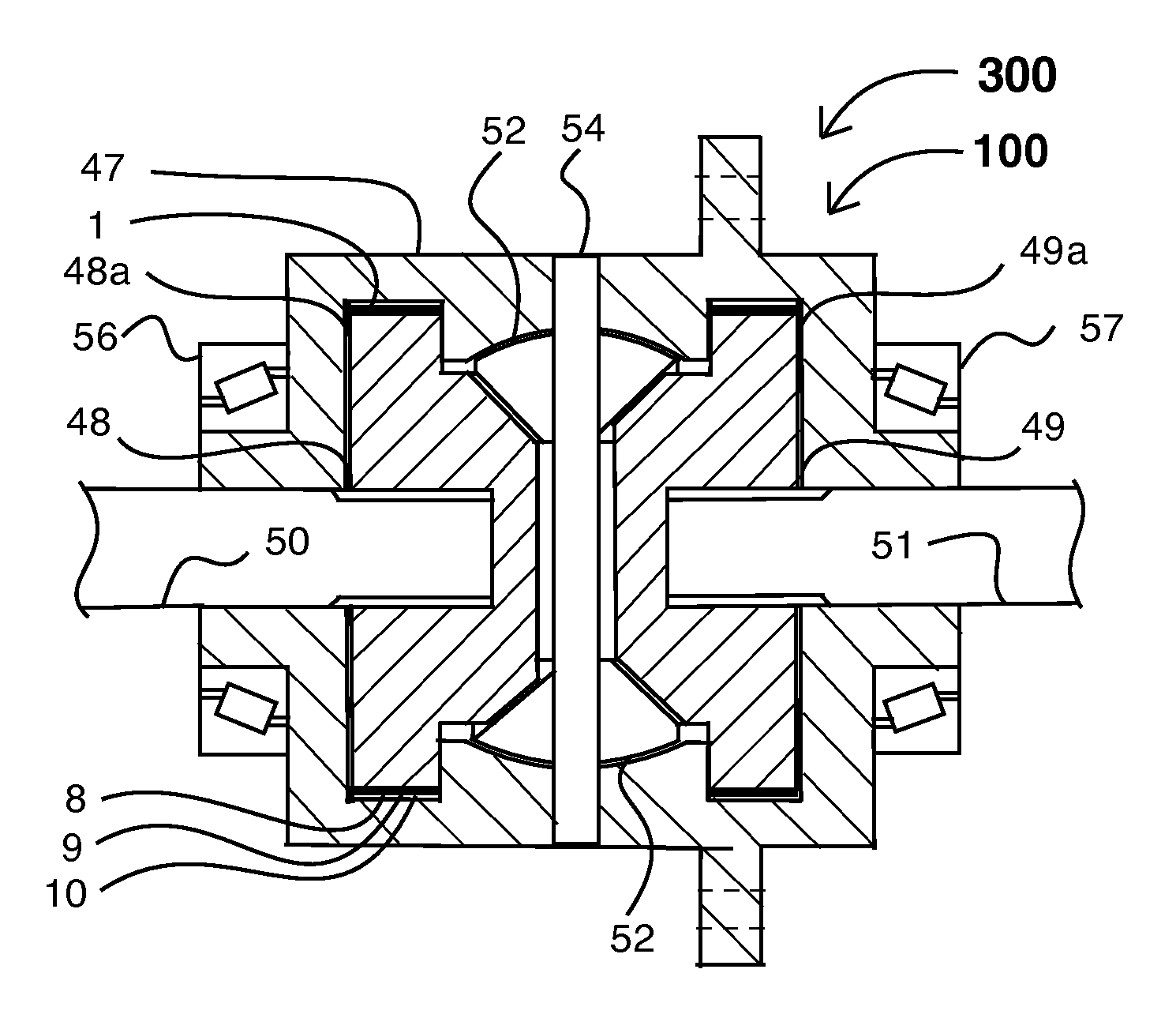
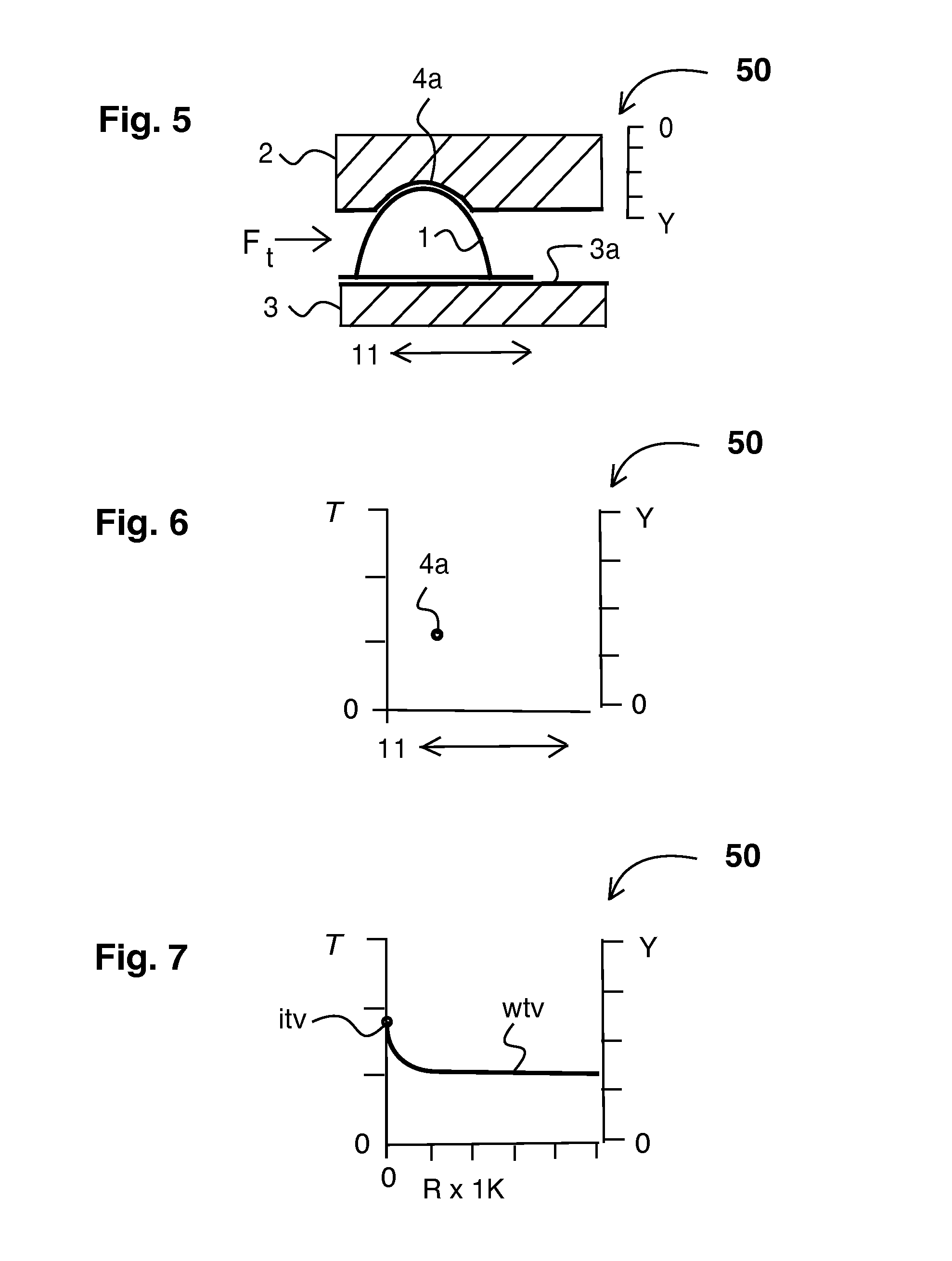
embodiment 50
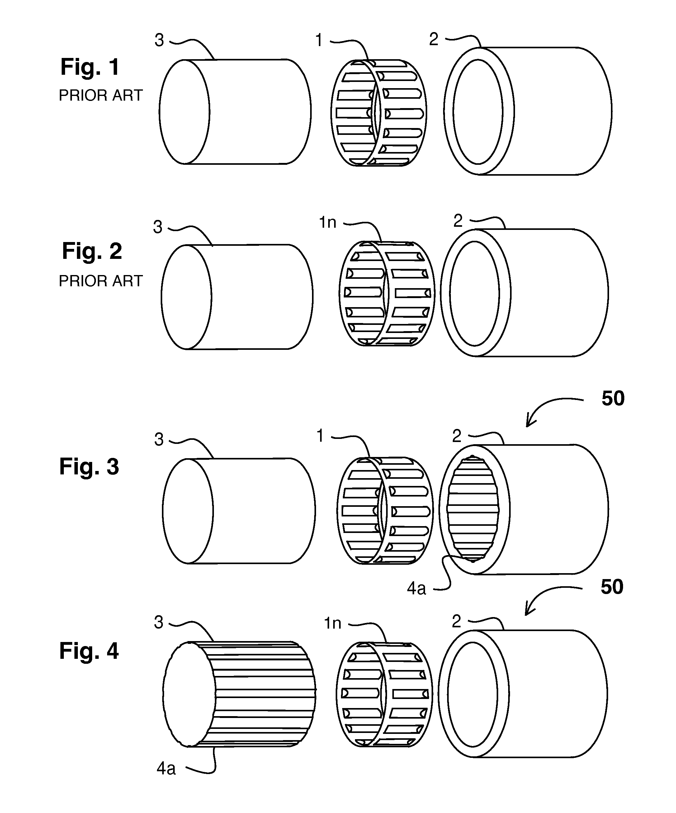
[0075]FIG. 3 shows an externally corrugated tolerance ring in an assembly in exploded perspective view relating to the present invention. Showing, preferred embodiment 50 of the present invention, externally corrugated tolerance ring 1, external cylindrical component 2, internal cylindrical component 3, constant value axial groove 4a. It is understood that when the torque limit of this assembly is exceeded either the, external cylindrical component 2, or the internal cylindrical component 3, will slip relative to the other. However as there is means to mechanically lock the corrugations of, externally corrugated tolerance ring 1, to external cylindrical component 2, by one or more corrugation in, constant value axial groove 4a, the desired internal cylindrical component 3, can slip and externally corrugated tolerance ring 1, will remain mechanically locked to, external cylindrical component 2, thus providing a torque limiting assembly assembly that is durable, simple and inexpensive...
embodiment 100
[0097]Explaining FIG. 8, it shows preferred embodiment 100 that provides a predetermined constant minimum torque-slip value at minimum value mechanical down ramp stop 8 under normal rotational conditions. As angular acceleration of internal cylindrical component 3 increases, preferably externally corrugated tolerance ring 1 is driven “down” down ramp 9 into decreasing clearance between down ramp 9, and internal cylindrical component 3, thus causing an increase in torque-slip value.
[0098]Thus preferably compression and torque increase until the corrugations reach maximum value mechanical down ramp stop 10, at which point the torque-slip threshold is reached. Should angular acceleration continue, preferably preferred embodiment 100 functions as a torque limiter thereby providing a predetermined maximum torque-slip value. Preferably because down ramp 9, has a self-releasing profile and because angular acceleration ceases or becomes negative, externally corrugated tolerance ring 1, retu...
embodiment 600
[0123]Explaining FIG. 14, it shows preferred embodiment 600 in a configuration that provides zero torque-slip under normal conditions. Axial compression groove 4b can engage one or more corrugations of externally corrugated tolerance ring 1, and as external compression component 2c is moved by housing moving force mF, the decreasing dimension between external compression component 2c, internal cylindrical component 3, and internal cylindrical component surface 3a, causes an increase in compression and torque-slip value.
[0124]Thus preferably compression and torque-slip increase until said external compression component 2c reaches external compression component stop 10x, at which point maximum desired torque-slip value is reached. Preferably preferred embodiment 600 then functions as a torque limiter, thereby providing a predetermined maximum torque-slip value. Preferably because axial compression groove 4a has a self-releasing profile and or because housing moving force mF ceases or ...
PUM
 Abstract
Description
Claims
Application Information