
Torque limiting system

a technology of torque limit and limiting system, which is applied in the direction of couplings, slip couplings, gearing, etc., can solve the problems of high-frictional loading

Inactive Publication Date: 2018-11-13
BAIR LING TECH LLC
View PDF37 Cites 6 Cited by
  • Summary
  • Abstract
  • Description
  • Claims
  • Application Information

AI Technical Summary

Benefits of technology

[0010]It is a further object and feature of the present invention to provide such a system permitting independent rotation between the two driven axles, or two output shafts in a fashion that employs tolerance rings as simple, durable and cost-effective means of providing fixed, variable, adjustable and active torque limiting assemblies which provide predetermined amounts of torque internal to the differential, that resist the relative motion of the output shafts so as to desirably distribute torque should traction be compromised on one output shaft or drive wheel.
[0011]It is a further object and feature of the present invention to provide versatile, simple, durable, inexpensive system of limited slip differentials:
[0015]that permits independent rotation between the two driven axles, or two output shafts in a fashion that employs tolerance rings as simple, durable and cost-effective means of increasing versatility and functionality of torque limiters and limited-slip differentials in automotive and industrial drive lines;
[0017]that permits independent rotation between the two driven axles, or two output shafts in a fashion that provides long service life;
[0022]It is a further object and feature of the present invention to provide a system having axial grooves which provide mechanical forces that can hold said corrugations in said grooves, and prevent the rotation of the tolerance rings corrugations against a circumferential component.
[0023]Notably said grooves can allow said tolerance ring to function reliably at a much wider and previously unavailable ranges of fixed and variable torque-slip values because spring force and friction is not required to prevent destructive rotation of said tolerance ring.

Problems solved by technology

When a Tolerance Ring is compressively assembled between said mating cylindrical components, each corrugation provides a spring force resulting in friction.
Many known to the art limited slip differentials utilize viscosity, locking devices, torque sensing gear systems, frictional clutch plates or cones, or other means to limit differentiation and are expensive, complex, heavy, and may exhibit high-frictional loading.

Method used


Image

  • Torque limiting system
  • Torque limiting system
  • Torque limiting system

Examples


embodiment 50

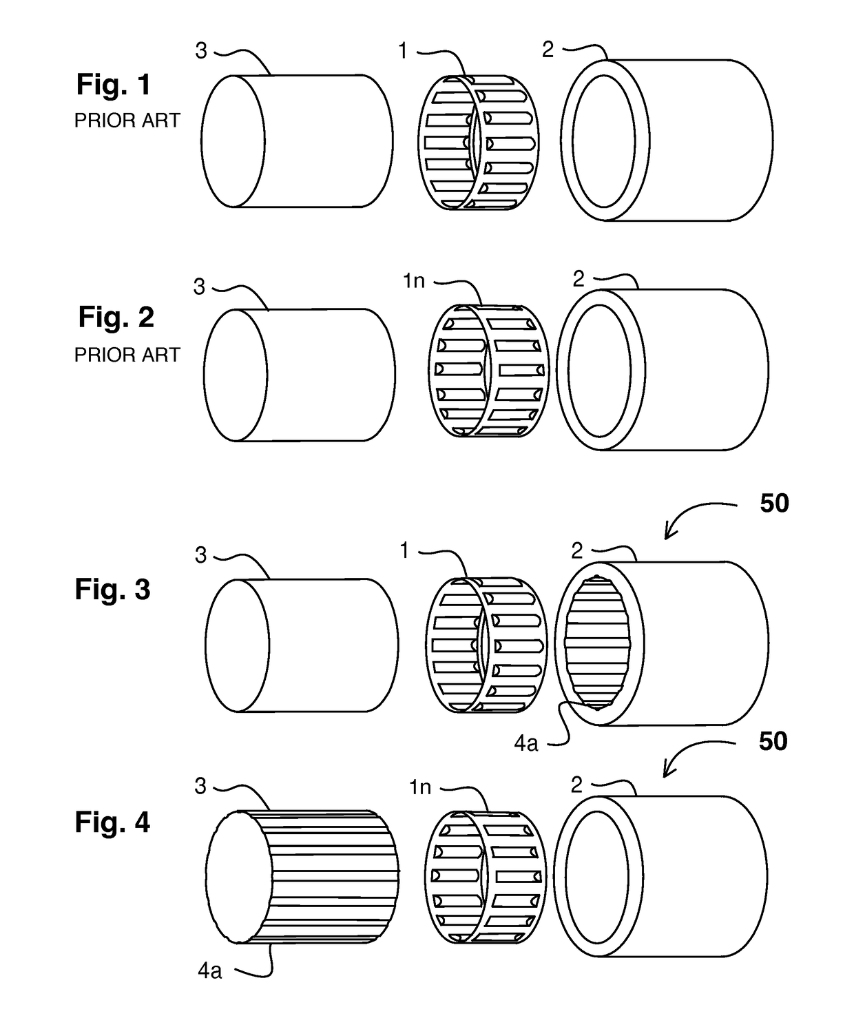
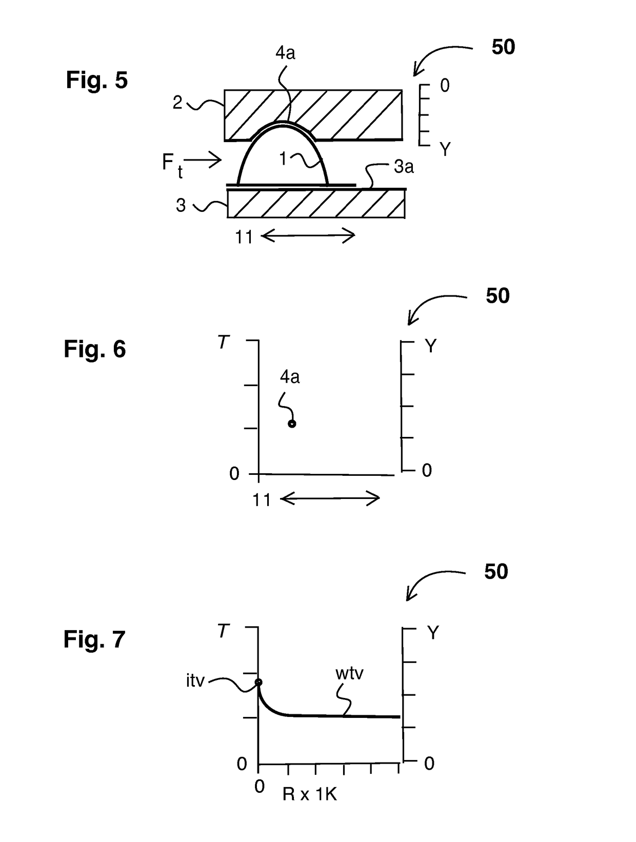
[0075]FIG. 3 shows an externally corrugated tolerance ring in an assembly in exploded perspective view relating to the present invention. Showing, preferred embodiment 50 of the present invention, externally corrugated tolerance ring 1, external cylindrical component 2, internal cylindrical component 3, constant value axial groove 4a. It is understood that when the torque limit of this assembly is exceeded either the, external cylindrical component 2, or the internal cylindrical component 3, will slip relative to the other. However as there is means to mechanically lock the corrugations of, externally corrugated tolerance ring 1, to external cylindrical component 2, by one or more corrugation in, constant value axial groove 4a, the desired internal cylindrical component 3, can slip and externally corrugated tolerance ring 1, will remain mechanically locked to, external cylindrical component 2, thus providing a torque limiting assembly that is durable, simple and inexpensive.

[0076]FI...

embodiment 100

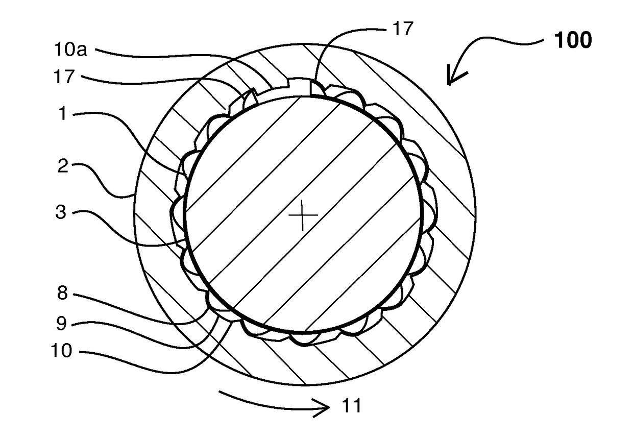
[0097]Explaining FIG. 8, it shows preferred embodiment 100 that provides a predetermined constant minimum torque-slip value at minimum value mechanical down ramp stop 8 under normal rotational conditions. As angular acceleration of internal cylindrical component 3 increases, preferably externally corrugated tolerance ring 1 is driven “down” down ramp 9 into decreasing clearance between down ramp 9, and internal cylindrical component 3, thus causing an increase in torque-slip value.

[0098]Thus preferably compression and torque increase until the corrugations reach maximum value mechanical down ramp stop 10, at which point the torque-slip threshold is reached. Should angular acceleration continue, preferably preferred embodiment 100 functions as a torque limiter thereby providing a predetermined maximum torque-slip value. Preferably because down ramp 9, has a self-releasing profile and because angular acceleration ceases or becomes negative, externally corrugated tolerance ring 1, retu...

embodiment 600

[0123]Explaining FIG. 14, it shows preferred embodiment 600 in a configuration that provides zero torque-slip under normal conditions. Axial compression groove 4b can engage one or more corrugations of externally corrugated tolerance ring 1, and as external compression component 2c is moved by housing moving force mF, the decreasing dimension between external compression component 2c, internal cylindrical component 3, and internal cylindrical component surface 3a, causes an increase in compression and torque-slip value.

[0124]Thus preferably compression and torque-slip increase until said external compression component 2c reaches external compression component stop 10x, at which point maximum desired torque-slip value is reached. Preferably preferred embodiment 600 then functions as a torque limiter, thereby providing a predetermined maximum torque-slip value. Preferably because axial compression groove 4a has a self-releasing profile and or because housing moving force mF ceases or ...


PUM


Abstract

The present invention relates to torque transfer and torque limiting system technology and applications. This invention relates to providing improved torque limiting systems that employ tolerance rings for controlling transmitting power between a single power-input shaft and one or more power-output shafts, which can protect mechanical equipment and drivetrains from damage by mechanical overload. Relating to motor vehicle differentials, the present invention can control differentiation between two power-output shafts, or drive shafts by providing friction internal to said differential and limit “undesirable” slip or differentiation between wheels, as might occur when one wheel encounters a low-traction condition, providing a limited-slip differential.

Description

CROSS REFERENCE TO RELATED APPLICATIONS[0001]The present application is related to and claims priority from prior provisional application Ser. No. 61 / 880,178 filed Sep. 20, 2013, entitled “Limited Slip Differential with Tolerance Rings / Circumferential Clutches”, 61 / 907,386, filed Nov. 22, 2013, entitled “Limited Slip Differential with Tolerance Rings”, and is related to and claims priority from prior provisional application Ser. No. 61 / 927,111, filed Jan. 14, 2014, entitled “Mechanical Locking System for Tolerance Rings”, the contents of which are incorporated herein by this reference and are not admitted to be prior art with respect to the present invention by the mention in this cross-reference section.BACKGROUND OF THE INVENTION[0002]1. Field of the Invention[0003]The present invention relates to torque limiting system technology, torque-slip and torque limiting devices and their application to power transmission assemblies. Such torque limiting devices can protect mechanical equ...

Claims


Application Information

Patent Timeline
Patent Type & Authority Patents(United States)
IPC IPC(8): F16H48/28F16D7/02
CPCF16D7/021F16H48/28F16D1/0835F16D1/0864F16D2001/0955F16D7/048
Inventor LINGREN, RODRIC N.BAIR, DONALD L.
Owner BAIR LING TECH LLC
Learn More