Medical jiggle lag screw for medicine

A technology of screw and pulling force, which is applied in the field of medical micro-motion lag screws, and can solve the problems of easy breakage of screws and difficulty in taking out broken screw bone round needles.

Active Publication Date: 2011-10-12
BEIJING NATON TECH GRP CO LTD
View PDF4 Cites 0 Cited by
  • Summary
  • Abstract
  • Description
  • Claims
  • Application Information

AI Technical Summary

Problems solved by technology

The strength of ordinary screws and cannulated screws can meet the requirements of the static state of the joint, but the screws are easy to break at the joint space under the state of exercise and load-bearing
Removing a broken screw is as difficult as removing a broken bone pin

Method used


Image

  • Medical jiggle lag screw for medicine
  • Medical jiggle lag screw for medicine

Examples


Embodiment Construction

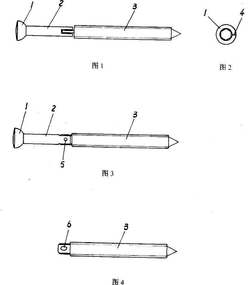
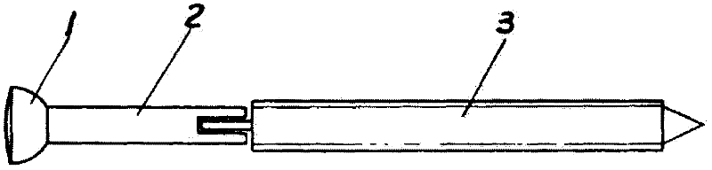
[0016] The present invention will be further described in detail below in conjunction with the accompanying drawings of the embodiments.

[0017] Referring to the accompanying drawings, the medical micro-motion lag screw provided by the present invention is an improvement on the basis of the existing locking nail, and its external structure size is the same as that of the original screw, with a rod diameter of 2.4-3 mm and a rod length of 50 mm. In the present invention, the screw rod of the screw is divided into two parts, and then the two parts are hinged together by a hinge shaft. As shown in the figure, there is no screw thread on the first section screw rod 2 that is made as one with the screw head 1, and the tail section screw rod 3 hinged with the first section screw rod 2 is full thread. Position mark 4 notches are set on the screw head 1 . The axis orientation of the hinge shaft 5 can be determined with reference to the positioning mark 4 . That is, when the screw i...


PUM


Abstract

A medical micromotion lag screw pertains to the technical field of surgical medical devices. The invention provides the medical micromotion lag screw which has anti-breaking function. The invention includes a screw head and a screw rod, the screw rod and the screw head are an integral body which is composed of a first section of the screw rod and a tail section of the screw rod by hinging. The screw rod of the medical micromotion lag screw which is provided by the invention adopts the structural form of hinging two sections, the hinged part between the two sections of the screw rods must guarantee that the two sections of the screw rods can have the micro-movement of 1 to 2mm along the radial direction and the axial direction mutually. The surgical method of using the screw for fixing is similar with the existing lab screw. The invention can not only ensure the firm fixation of amphiarthrosis, but also ensure the micro-movement of the joint; furthermore, the screw rod of the screw adopts the structure mode of hinging two sections, which can effectively prevent the screw rod from breaking due to stress concentration, thereby avoiding the troublesome which is caused by removing the broken screw and avoiding the unnecessary pain of patients. Therefore, the screw is an ideal alternative product of the existing lab screw.

Description

technical field [0001] The invention relates to a medical micro-motion lag screw, which belongs to the technical field of surgical instruments. Background technique [0002] There are many fretting joints (joints) in the human body, such as the inferior tibiofibular syndesmosis, superior tibiofibular syndesmosis, acromioclavicular joint, sternoclavicular joint, pubic symphysis, sacroiliac joint, and spinoface joint. Often these joints have micromotions of a few millimeters. Once these joints are damaged, they need to be immobilized. Fixation methods include bone circular pins, ordinary screws, hollow screws, steel plates and their screws. The strength of the bone circular needle is low, and it is easy to break at the fretting joint space. Clinically, the bone circular needle breaks and wanders occasionally occurs, and it is very difficult to take out the broken bone circular needle. There are also reports in the literature that the traveling bony round needles stabbed imp...

Claims


Application Information

Patent Timeline
Patent Type & Authority Patents(China)
IPC IPC(8): A61B17/86
Inventor 张英泽张国川李西成
Owner BEIJING NATON TECH GRP CO LTD
Why Eureka
Try Eureka