Brush manufacturing machine

A technology for manufacturing machines and brushes, which is applied in the direction of brushes, brush bodies, household appliances, etc., which can solve the problems of high cost and achieve the effect of fast conveying movement

Inactive Publication Date: 2008-07-30
ZAHORANSKY AG
View PDF0 Cites 14 Cited by
  • Summary
  • Abstract
  • Description
  • Claims
  • Application Information

AI Technical Summary

Problems solved by technology

Usually such positioning devices are designed for the application and require a considerable expense for re-equipment with other brush styles

Method used


Image

  • Brush manufacturing machine
  • Brush manufacturing machine
  • Brush manufacturing machine

Examples


Embodiment Construction

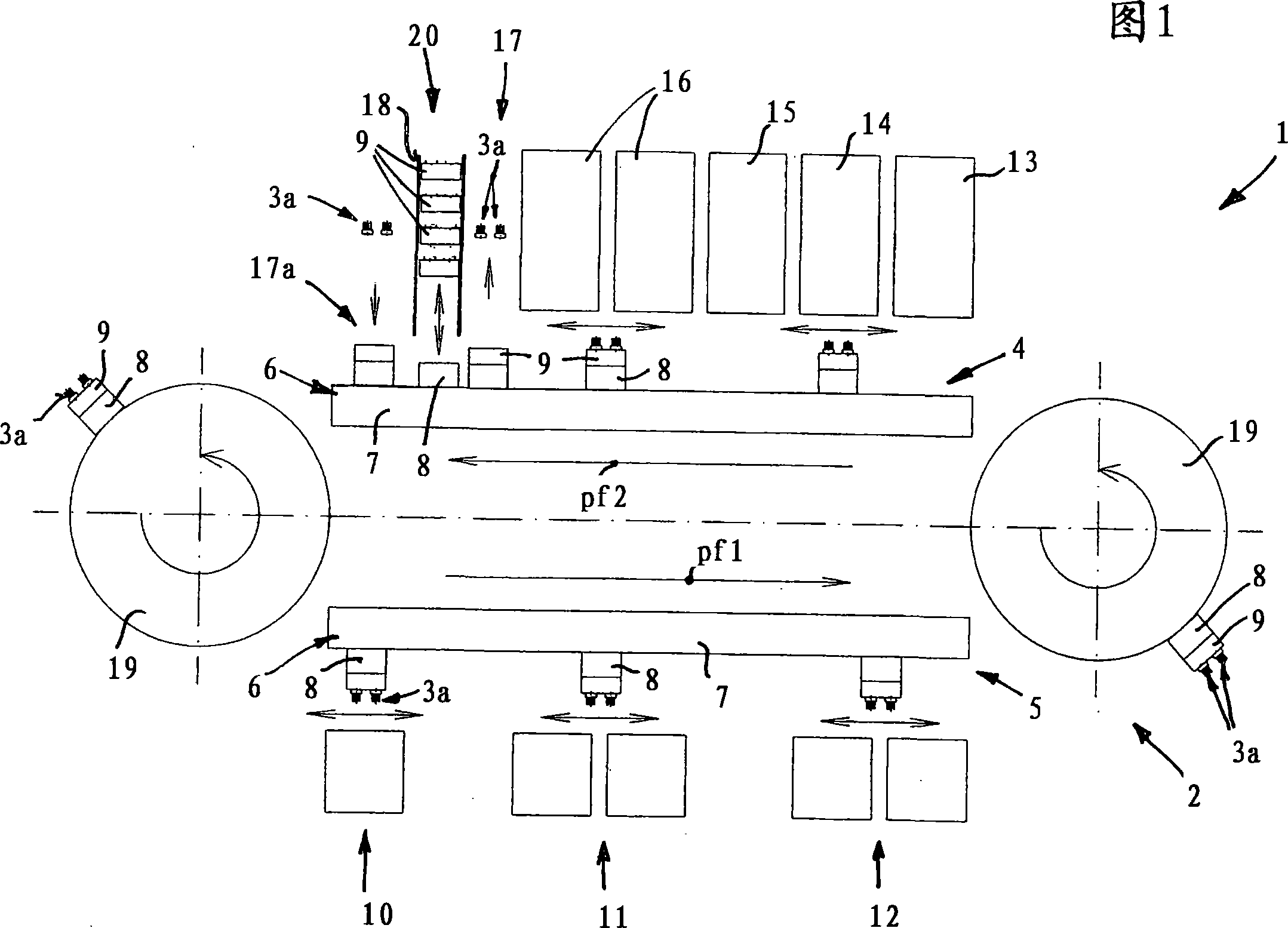
[0025] The brush production machine 1 shown in FIG. 1 has a conveyor 2 for brushes 3a, wherein processing stations are arranged along the conveyor. The conveying device 2 is designed as an endless conveying device and has two conveying parts 4 and 5 arranged approximately parallel to one another in the exemplary embodiment, each having at least one linear motor 6 .

[0026] The linear motors 6 each have a stator 7 extending substantially along the conveying section, on which a plurality of runners 8 are movable independently of one another.

[0027] Each mover 8 is air-bearing, so that it moves without contact and without wear via an air cushion formed between the mover and the stator.

[0028] Since the movers 8 are held magnetically on the stator 7, an arbitrary configuration and thus an overhead configuration of the linear motor is also possible. There is thus a high degree of flexibility in the construction of the brush manufacturing machine, since its position can be ada...


PUM


Abstract

A brush production machine has a conveyor (2) for brush bodies (3) or brushes (3a), wherein a plurality of processing stations (10 to 16) are arranged along the conveyor. The conveying device (2) has at least one conveying part (4, 5) comprising a linear motor (6), which is designed for conveying the brush bodies (3) or brushes (3a) and for processing them in at least one location in the station.

Description

technical field [0001] The invention relates to a brush manufacturing machine comprising a conveyor for brush bodies or brushes, wherein a plurality of processing stations are arranged along the conveyor. Background technique [0002] It is known to use an endless chain for the conveyor device, which chain comprises a plurality of grippers for the brush bodies or brushes fixed thereon. A transport of brush bodies or brushes from one processing station to the next is thereby possible. The further conveying takes place synchronously, so that the processing station with the longest processing time prescribes the conveying cycle. [0003] In machining stations, machining movements, ie back and forth movements or continuing positioning movements, are often required. Due to the chain connection of the brush bodies or the holders for the brushes, the machining tool has to carry out these movements itself, but this usually entails a high outlay. As positioning devices, for exampl...

Claims


Application Information

Patent Timeline
Patent Type & Authority Applications(China)
IPC IPC(8): A46D3/08A46D3/00
CPCA46D3/08
Inventor 吉多·佐默
Owner ZAHORANSKY AG
Why Eureka
Try Eureka