
Card board structure for electric connector

A technology for electrical connectors and card boards, which is applied in the direction of connection, parts and circuits of connecting devices, and can solve the problems of occupying space and inconvenient structure of ear buckles.

Inactive Publication Date: 2008-08-06
蔡周旋
View PDF0 Cites 0 Cited by
  • Summary
  • Abstract
  • Description
  • Claims
  • Application Information

AI Technical Summary

Problems solved by technology

[0004] It is inconvenient to reach in and pull the ear buckle structure when the interface board is larger, or the pressing part of the ear buckle structure must avoid the interface board, so it needs to protrude to one side, which will take up space

Method used


Image

  • Card board structure for electric connector
  • Card board structure for electric connector
  • Card board structure for electric connector

Examples


Embodiment Construction

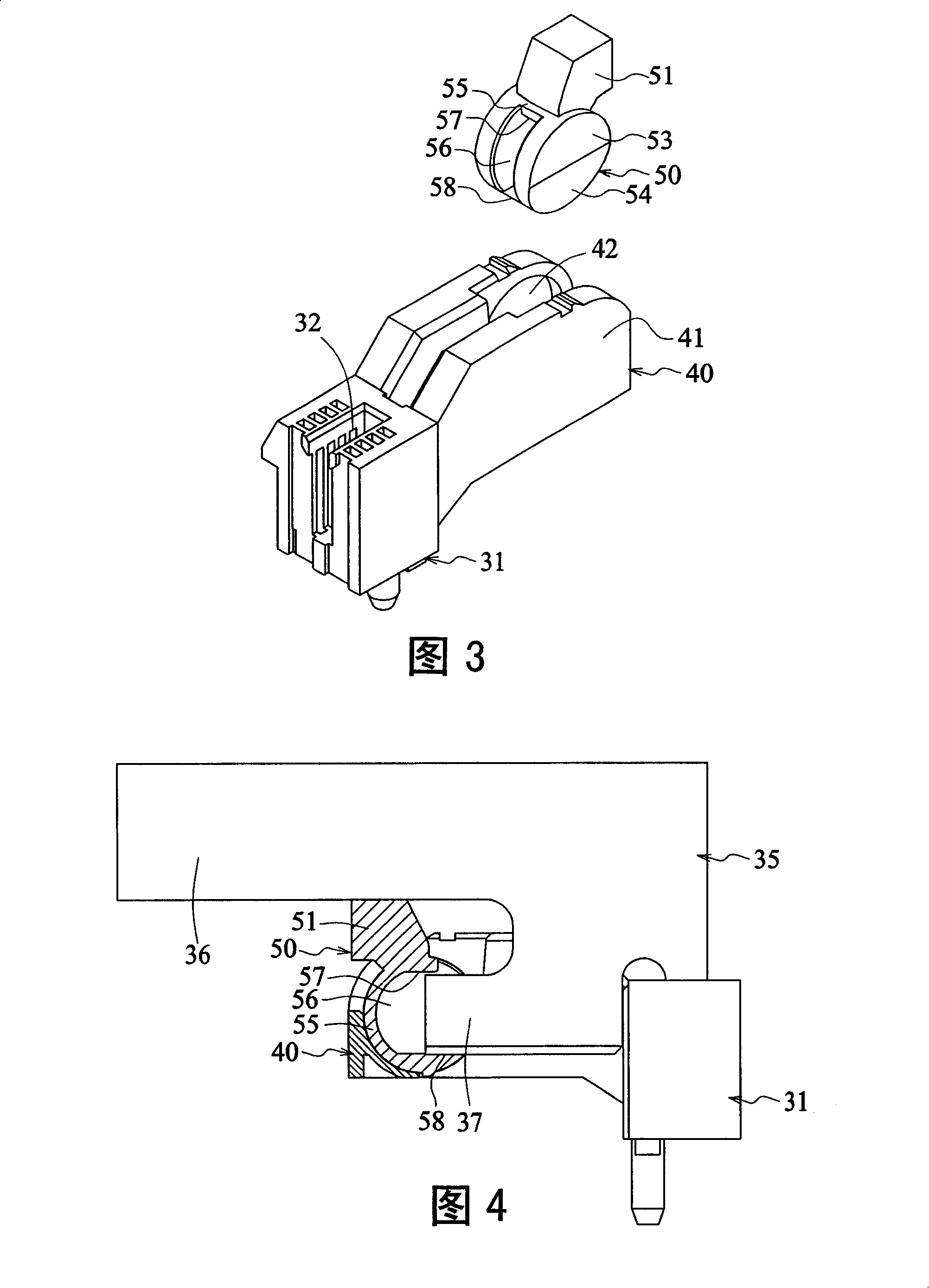
[0023] Please refer to Fig. 3 and Fig. 4, the card board structure of the electrical connector of the present invention, it is used for locking the interface board that inserts into electrical connector, and this electrical connector is provided with a lengthwise plastic seat body 31, and this plastic seat body 31 is provided with a slot 32 extending longitudinally, and this slot 32 can be inserted into an interface board 35, and one side of the interface board 35 is provided with a first protruding portion 36 and a second protruding portion 37 protruding laterally, A convex part 36 is higher and protruding than the second convex part 37, and the clip structure is provided with: a pivot seat 40 and a buckle assembly 50, wherein:

[0024] The pivot seat 40 is disposed at one end of the plastic seat body 31 , and has two side walls 41 , each of which has a pivot slot 42 .

[0025] The buckle assembly 50 is provided with a main body 55, two pivotal parts 53 and a plugging project...


PUM


Abstract

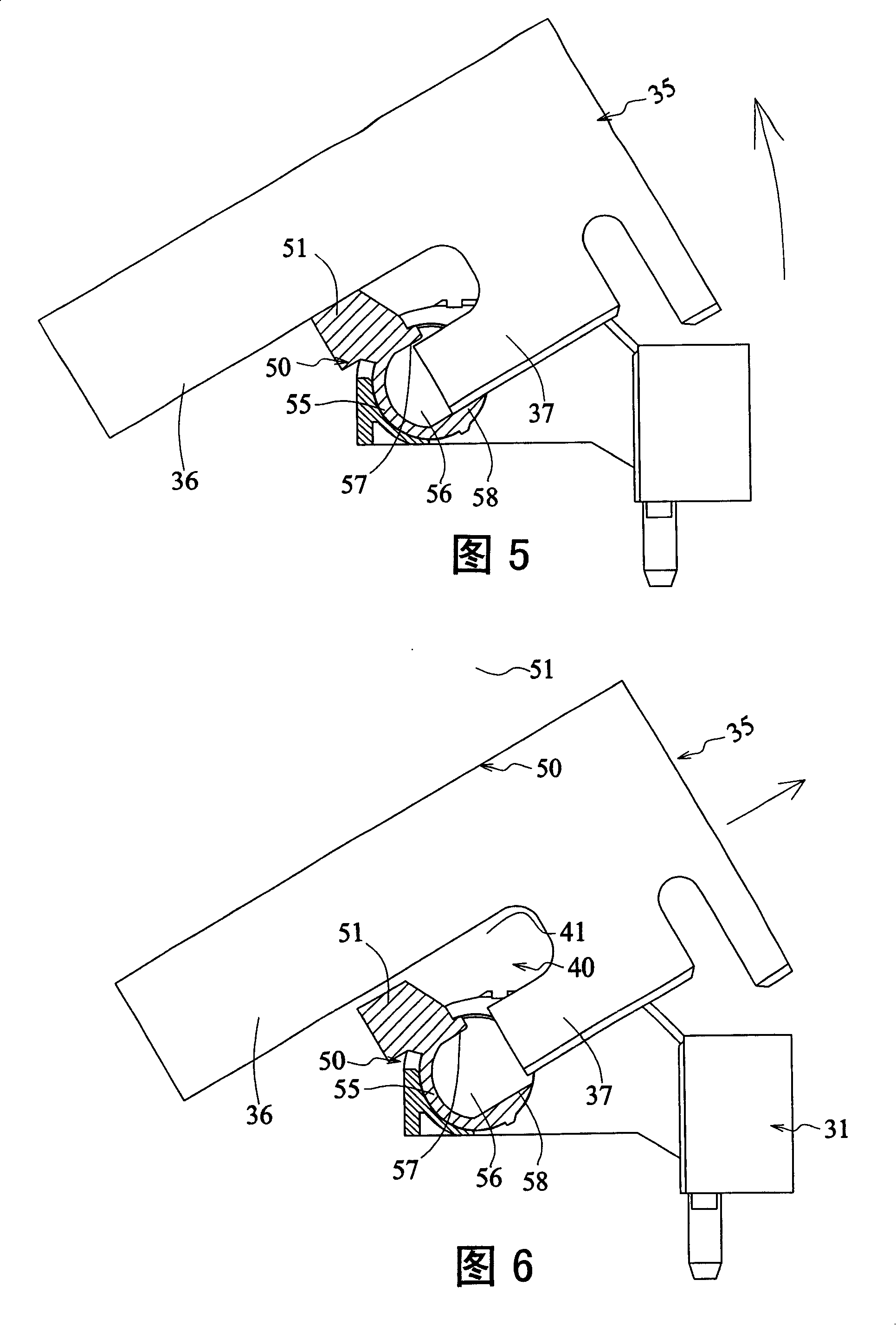
The present invention discloses a clamping plate structure of an electric connector, which is used to clamp an interface board inserted in the electric connector. The electric connector is provided with a plastic seat body; a slot is arranged on the plastic seat body; the interface board can be inserted in the slot; one end of the interface board is provided with a first convex part and a second convex part which protrude laterally; the first convex part is higher and more convex than the second convex part. The clamping plate structure is provided with an articulating seat arranged at one end of the plastic seat body, as well as a clamping component which is provided with a main body, an articulating part and a convex stuffing block; the articulating part is arranged on one side of the main body so as to be articulated with the articulating seat; the main body is provided with a concave part; the upper end of the concave part is provided with a clamping plate part; the lower end of the concave part is provided with a top plate part; the convex stuffing block is arranged above the main body. When the interface board is inserted, the clamping plate part clamps the second convex part of the interface board, and the top plate part pushes against the underside of the second convex part of the interface board, so as to ensure that the second convex part is clamped in the concave part; the lower edge of the first convex part of the interface board pushes against the stuffing block. When the other end of the interface board rotates upwards and can be pulled out in oblique direction, the interface board synchronously drives the main body to pivot to the top plate part and to be in an up-warp state, ensuring the clamping component is positioned on the position for an insert plate.

Description

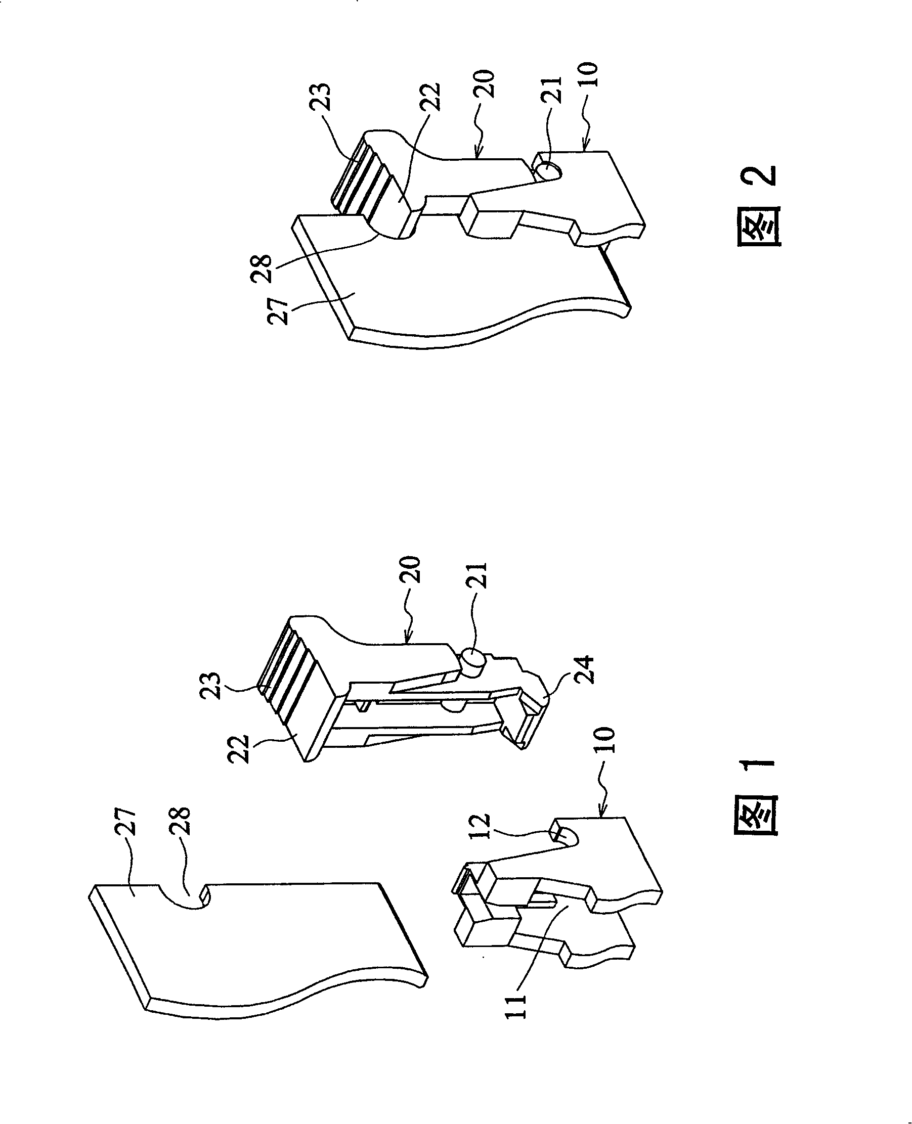
technical field [0001] The invention relates to an electrical connector, in particular to a card board structure of the electrical connector. Background technique [0002] Please refer to Fig. 1 and Fig. 2, it is a kind of existing electric connector that connects the interface board, and it comprises plastic base body 10 and ear buckle structure 20, wherein: the plastic base body 10 is arranged with a plurality of terminals (Fig. not shown), each of its two sides is provided with an accommodation groove 11, and the two sides of the accommodation groove are provided with pivot holes 12; the two sides of the earbuckle structure 20 are provided with pivot shafts 21 so as to be pivotally connected to the plastic seat The pivot hole 13 of the accommodating groove 11 of 10 has a buckle part 22 protruding into the seat and a pressing part 23 protruding out of the seat at its upper end, and the buckle part 22 can be locked on the interface plate 27 One side clamping hole 28 is pro...

Claims


Application Information

Patent Timeline
Patent Type & Authority Applications(China)
IPC IPC(8): H01R13/629
Inventor 蔡周旋
Owner 蔡周旋
Learn More