Car lamp control method and control circuit

A vehicle lamp control and vehicle lamp technology, which is applied in the direction of electric lamp circuit layout, energy saving control technology, electric light source, etc., can solve the problems of increasing the number of circuit board components, high failure rate, adverse effects on lines and life, and eliminates peak current. Effect

Inactive Publication Date: 2008-08-13
LIANCHUANG AUTOMOBILE ELECTRONICS
View PDF0 Cites 8 Cited by
  • Summary
  • Abstract
  • Description
  • Claims
  • Application Information

AI Technical Summary

Problems solved by technology

This method increases the number of components on the board and has a high failure rate
[0003] On the other hand, the car power supply is not always stable at the rated voltage of the lamp. Under certain con

Method used


Image

  • Car lamp control method and control circuit

Examples


Embodiment Construction

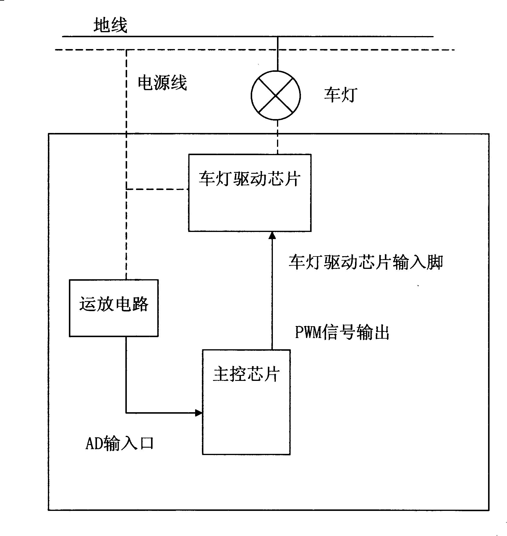
[0012] The present invention will be described in further detail below in conjunction with the accompanying drawings.

[0013] The car light control circuit shown in Figure 1 mainly includes two parts: the main chip and the car light driver chip. When the headlight lighting switch is turned on, the turn-on signal is transmitted to the main control chip, and the main control chip sends a PWM signal, that is, a pulse-width modulation signal (Pulse-Width-Modulation), to the input port of the light driver chip that controls the light. ;During the start-up process of the car light, the duty ratio of the PWM signal gradually increases according to a certain linear relationship with time, so that the voltage at both ends of the car light gradually increases until the voltage at both ends of the car light is equal to the rated voltage of the car light, and then remains at the car light Lamp rated voltage value. According to the load characteristics of the lights, within a certain per...


PUM


Abstract

The invention discloses a controlling method of vehicle light and corresponding control circuit of vehicle light, which is capable of eliminating peak current when the vehicle light is started. The invention output PWM signal, namely pulse width modulation signal, by main control chip to vehicle light driving chip; during startup of the vehicle light, duty cycle of the PWM signal is adjusted, thus duty cycle of PWM signal is increased gradually with time, so that voltage upon vehicle light is increased with time, until the voltage upon vehicle light is equal to rated voltage of vehicle light. The provided method of the invention makes voltage of the vehicle light increase gradually from 0V to rated, which realizes smooth transition of filament current, and eliminate peak current when vehicle starts up.

Description

technical field [0001] The present invention relates to a method for controlling a vehicle lamp and its corresponding control circuit, in particular to a method for controlling the voltage and current of a motor vehicle lamp and its corresponding control circuit. Background technique [0002] Automobile headlights will generate an instantaneous peak current during start-up, which is about 10 to 15 times the normal operating current. On the one hand, the peak current has a great impact on the battery, and it will also cause an overcurrent impact on the lamp circuit, and at the same time shorten the normal service life of the lamp. There are two current processing methods: one is to provide a large amount of redundancy to the drive circuit, for example, the normal operating current of a single dipped beam is 4.8A, then select a power chip with a maximum drive capacity of 60A to ensure that the headlights When starting multiple times, the driver chip will not be overloaded. A...

Claims


Application Information

Patent Timeline
IPC IPC(8): H05B37/02H05B39/02H05B39/09
CPCY02B20/42Y02B20/40
Inventor 张晔单津晖罗来军郭凤龙
Owner LIANCHUANG AUTOMOBILE ELECTRONICS
Why Eureka
Try Eureka