
Indoor unit of air-conditioner

A technology for air conditioners and indoor units, applied in air conditioning systems, airflow control components, space heating and ventilation details, etc., can solve problems such as inability to ensure exhaust volume and exhaust characteristics, and achieve the effect of preventing dust pollution

Inactive Publication Date: 2008-08-13
TOSHIBA CARRIER CORP
View PDF2 Cites 6 Cited by
  • Summary
  • Abstract
  • Description
  • Claims
  • Application Information

AI Technical Summary

Problems solved by technology

Specifically, since the centrifugal fan is a multi-blade type having a large number of blades and a narrow gap between the blades, the fan tends to be clogged by dust accumulated between the blades, and due to this effect, the originally intended discharge cannot be ensured. Problems with gas volume and exhaust characteristics

Method used


Image

  • Indoor unit of air-conditioner
  • Indoor unit of air-conditioner
  • Indoor unit of air-conditioner

Examples


Embodiment Construction

[0039] Referring now to the accompanying drawings, a first embodiment of the present invention will hereinafter be described in detail.

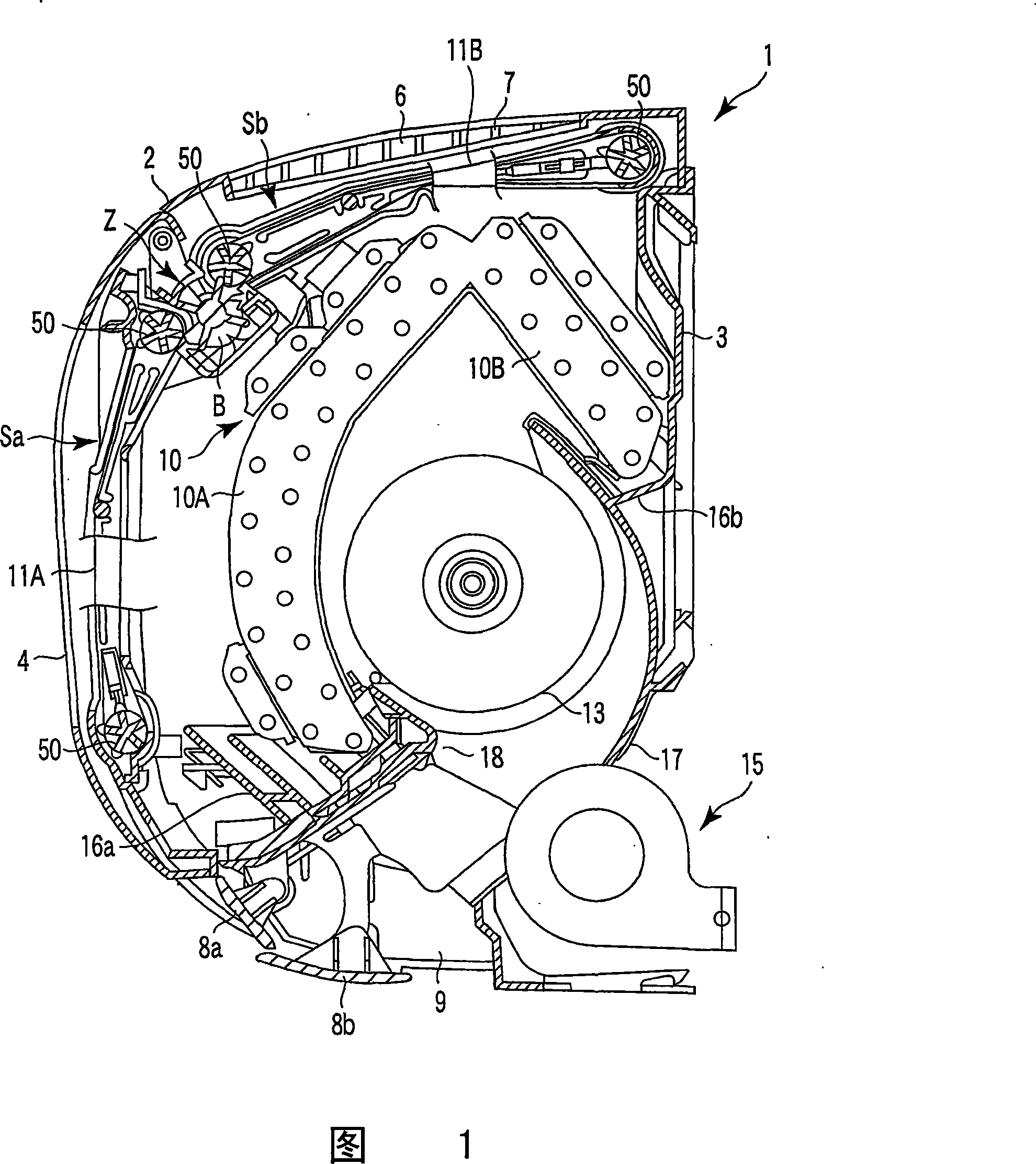
[0040] FIG. 1 is a schematic longitudinal sectional view partially schematically showing an indoor unit of an air conditioner.

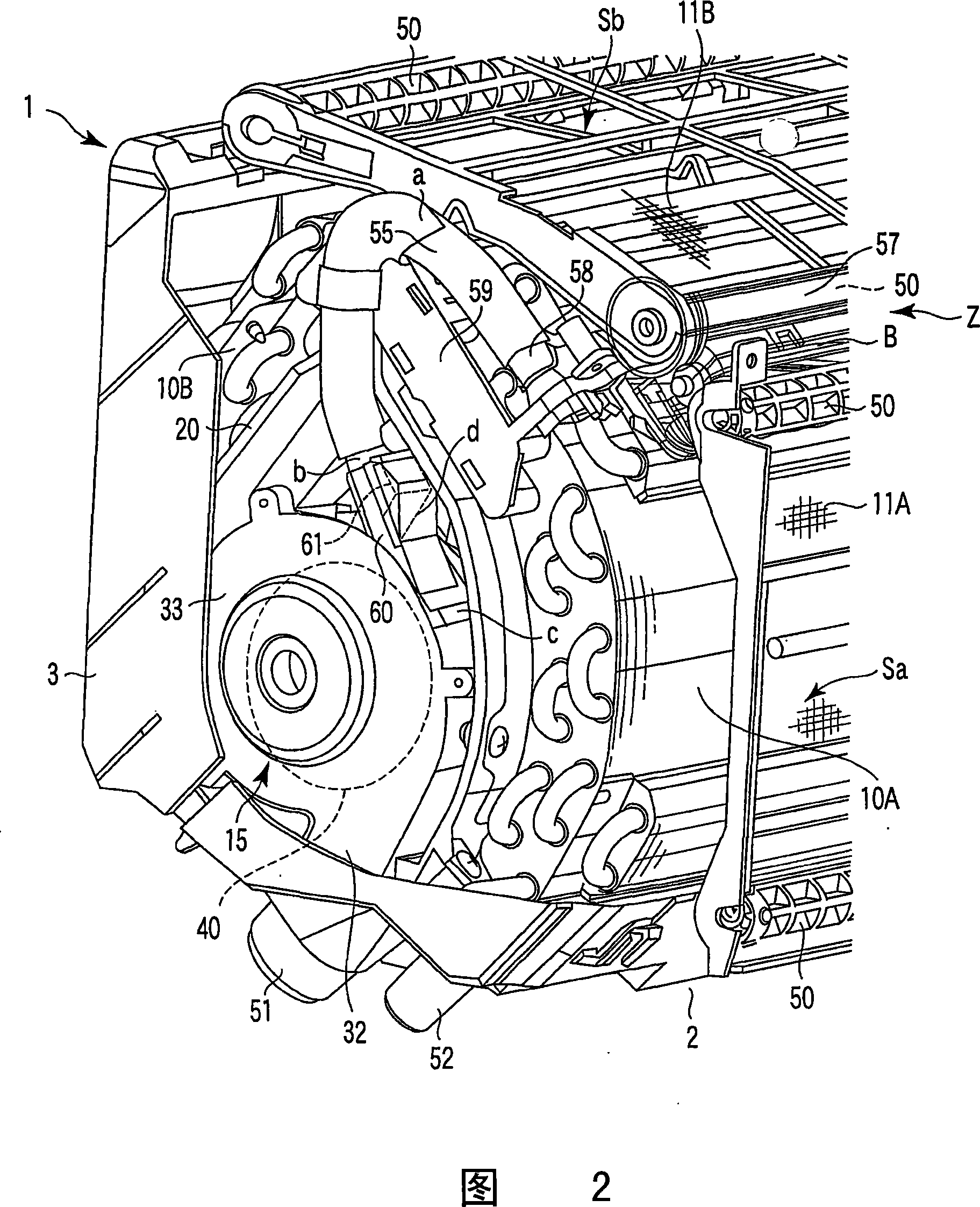
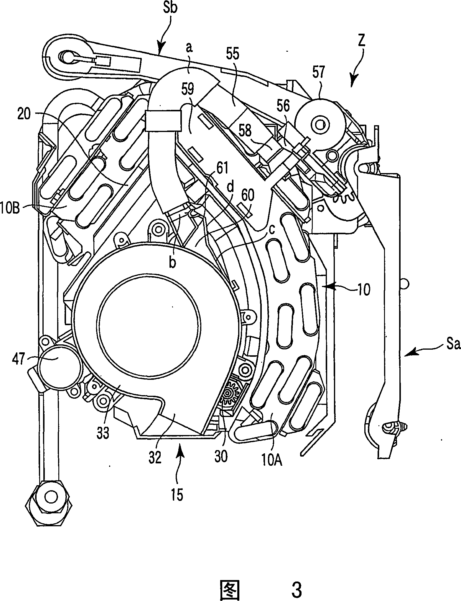
[0041] 2 is a perspective view with the front panel 2 of the indoor unit body 1 removed to show the inside, and FIG. 3 is a side view with the rear panel case 3 of the indoor unit body 1 removed. (Parts not given reference numerals are not described in the specification. The same principle applies hereinafter.)

[0042] The indoor unit body 1 is constituted by a front panel 2 and a rear panel case 3 and forms a horizontally long shape. On a part of the front side of the front panel 2, a front suction port 4 is opened and a movable panel supported to an opening / closing drive mechanism is fitted. When the operation stops, the movable panel is flush with the front panel 2 and closes the front suction port 4. During o...


PUM


Abstract

Suction ports 4 and 6 and a blowoff port 9 are equipped on a ventilation passage between the suction ports 4 and 6 and blowoff port 9, a heat exchanger 10 and a blower 13 are arranged to an indoor unit proper 1, and air filters 11A and 11B are mounted between the suction port and the heat exchanger. In addition, a ventilation unit 15 which discharges indoor air to the outside is equipped, and air filters have a sweeping unit Z which removes dust adhering to the air filter surfaces and collects it in a dust box. The ventilation unit has a fan casing on which an intake port 31 and an exhaust port 32 are provided, an exhaust fan 35, and a connection hose 55 which communicates with a dust box of the sweeping unit and the ventilation unit, wherein the head end portion of the connection hose is connected to the outer circumferential portion upstream of the exhaust port of the fan casing.

Description

technical field [0001] The present invention relates to an indoor unit of an air conditioner, and more particularly, to a discharge structure that removes dust from an air filter and discharges the removed dust to the outside. Background technique [0002] In the indoor unit of the air conditioner, indoor air is sucked from the suction port to the indoor unit proper, and air contained in the indoor air is captured by an air filter installed opposite to the suction port, and the indoor air are individually directed to the heat exchanger and exchanged heat. As the air conditioner continues to operate, trapped dust accumulates on the air filter, and when left unchecked, circulation of room air to the heat exchanger is disrupted and results in less efficient heat exchange. [0003] It is desirable to periodically remove dust adhering to the air filter and improve heat exchange efficiency. Therefore, the front panel constituting the front surface of the indoor unit body is rota...

Claims


Application Information

Patent Timeline
IPC IPC(8): F24F1/00F24F1/0041F24F1/0057F24F1/0063F24F1/0067F24F1/0073F24F1/0083F24F8/10
CPCF24F1/0007F24F2001/0055F24F1/0022F24F1/0025F24F3/1603F24F1/0033F24F2001/0048F24F2003/1639F24F1/0057F24F1/0041F24F8/90F24F8/10F24F1/0067F24F1/0073F24F1/0063F24F1/0083F24F1/00F24F13/28F24F13/10
Inventor 小泽哲朗铃木秀人佐野充邦三岛毅睦冈田觉竹谷伸行
Owner TOSHIBA CARRIER CORP
Learn More