Cast-in-situ hollow building roof construction method

A technology of hollow floor and construction method, which is applied in the direction of floors, building components, buildings, etc., and can solve the problems that are prone to not dense, easy to float, etc.

Active Publication Date: 2008-08-20
XINPU CONSTR GRP
View PDF0 Cites 24 Cited by
  • Summary
  • Abstract
  • Description
  • Claims
  • Application Information

AI Technical Summary

Problems solved by technology

[0003] In view of the above situation and the actual needs of the construction industry, the purpose of the present invention is to provide a new construction method for cast-in-place hollow floors, which can effectively solve the problem of construction of GRC prefabricated thin-walled pipes (i.e. hollow pipes, the same below) due to their light weight. It is easy to float in the middle, and the strength decreases when it encounters water. The concrete at the bottom of the thin-walled pipe (also called concrete, the same below) is prone to the problem of not being dense. Mark the pre-embedded position lines reserved for the installation of the inner frame beams and hidden beams, the position lines of the steel mesh, the bottom row of steel bars on the floor, and the control edge of the hollow pipe, start

Method used


Image

  • Cast-in-situ hollow building roof construction method
  • Cast-in-situ hollow building roof construction method

Examples


Embodiment Construction

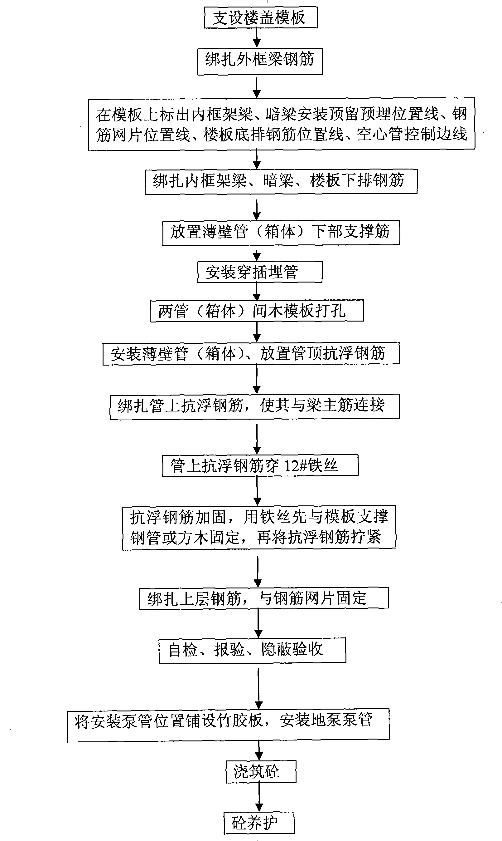
[0005] The present invention will be described in detail below in conjunction with the process flow diagram. Given by process flow chart, the present invention is realized by the following steps:

[0006] 1. Supporting floor formwork;

[0007] 2. Binding the steel bars of the outer frame beam;

[0008] 3. Mark the pre-embedded position lines reserved for the installation of inner frame beams and hidden beams, the position lines of steel mesh, the position lines of reinforcement bars at the bottom of the floor slab, and the control side lines of hollow pipes on the formwork;

[0009] 4. Binding inner frame beams, concealed beams, and steel bars under the floor;

[0010] 5. Place the supporting ribs at the lower part of the thin-walled pipe. After the bottom mesh steel bars are bound, place the supporting ribs at the lower part of the thin-walled pipes and connect them with the bottom bars of the beams. Set a 50mm thick concrete pad under the supporting ribs;

[0011] 6. Inst...


PUM


Abstract

The invention relates to a construction method for cast-in-cast hollow floors, which can effectively solve the problems that the GRC prefabricated thin-wall pipes in the construction are easy to upward float due to the light weights, the waterproof strength is reduced, and the concrete at the bottom of the thin-wall pipes is easy to get loosened. The invention adopts the technical proposal that: a formwork of the floor is raised; steel bars of an exterior frame beam are bundled; reserving and pre-burying lines of position for the installation of an internal frame beam and a hidden beam, lines of position for the reinforced net and the lower rows of steel bars of floorslabs, and controlling sidelines for hollow pipes are marked on the formwork; the internal frame beam, the hidden beam, the lower rows of steel bars of the floorslabs are bundled; reinforcements are arranged at the lower part of the thin-wall pipes; inserted and buried pipes are installed; holes are drilled on the wood formworks between two pipes; the thin-wall pipes are installed; the anti-floating steel bars on the top of the thin-wall pipes are placed, the anti-floating steel bars on the thin-wall pipes are then bundled; iron wires are firstly fixed with the support reinforcement of the formwork, and the anti-floating steel bars are tightly screwed, then an upper layer of steel bars is bundled to be fixed with the reinforced net; bamboo plywood and pumped pipes are respectively laid and installed; the concrete is cast and maintenance for the concrete is then carried out. The construction method for cast-in-cast hollow floor has the advantages of reducing engineering cost and having great economic and social benefits.

Description

1. Technical field [0001] The invention relates to the field of construction, in particular to a construction method for a cast-in-situ hollow floor. 2. Background technology [0002] With the continuous, stable and rapid development of my country's economy, the country's investment in construction has increased, the construction industry has achieved unprecedented development, and the overall technical level of the construction industry has been greatly improved. In order to adapt to the current development situation, the use of advanced new technologies in construction has become common. problems, but at the same time, there are also problems of one kind or another. Now take the commonly used thin-walled pipes or box-cast hollow floors as examples. The current GRC prefabricated thin-walled pipes are made of expensive paper pipes, hard plastic pipes, and thin-walled pipes. Made of corrugated steel pipes, the cost is very high. Due to the light weight and easy floating during ...

Claims


Application Information

Patent Timeline
IPC IPC(8): E04B5/16E04B5/32
Inventor 刘轶王麦对王旭风王建强刘昊纯
Owner XINPU CONSTR GRP
Why Eureka
Try Eureka