Method of producing exhaust-gas carrying devices, in particular exhaust-gas cleaning devices

A technology for cleaning device and exhaust gas, applied in the direction of exhaust device, muffler device, separation method, etc.

Active Publication Date: 2008-08-20
ARVINMERITOR EMISSIONS TECH GMBH
View PDF0 Cites 5 Cited by
  • Summary
  • Abstract
  • Description
  • Claims
  • Application Information

AI Technical Summary

Problems solved by technology

However, in practice it is almost impossible to compensate for large variations in the liner clamping force even by this means

Method used


Image

  • Method of producing exhaust-gas carrying devices, in particular exhaust-gas cleaning devices
  • Method of producing exhaust-gas carrying devices, in particular exhaust-gas cleaning devices
  • Method of producing exhaust-gas carrying devices, in particular exhaust-gas cleaning devices

Examples


Embodiment Construction

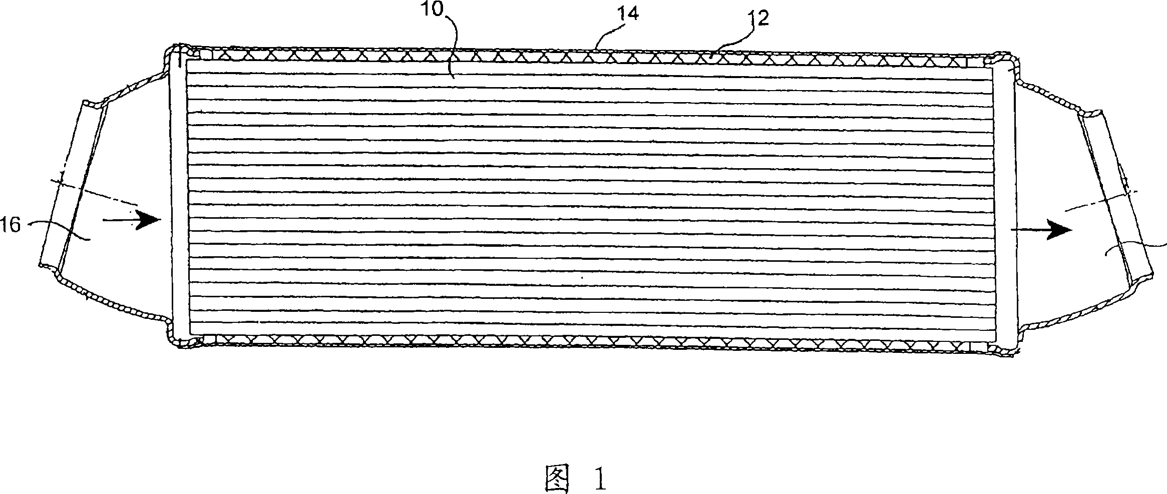
[0033] FIG. 1 illustrates an exhaust gas carrying device in the form of a vehicle exhaust gas cleaning device and accommodated in a motor vehicle. The vehicle exhaust gas cleaning device is an exhaust gas catalytic converter, or a diesel particle filter, or a combination of the two.

[0034] The core of the exhaust gas cleaning device is an elongated cylindrical substrate 10 comprising, for example, a ceramic substrate or a wrapped, corrugated plate or other catalytic carrier or filter material with or without coating . The substrate 10 may have a cylindrical cross-section or a non-circular cross-section. To simplify illustration, a cylindrical cross section is shown in each figure. The substrate is surrounded by a liner 12 , wherein the liner 12 serves as an elastic compensating element between the substrate 10 and the outer cover 14 . The housing 14 is designed with a low wall thickness, in particular it is made of sheet metal. An inlet funnel 16 and an outlet funnel 18 ...


PUM


Abstract

In a method for producing exhaust-gas-conducting devices, in particular exhaust-gas-cleaning devices, the outer geometry of each substrate (10) is determined and, as a function of this outer geometry, an outer housing (14) with coordinated geometry is manufactured, in which the substrate (10) is accommodated and clamped together with a compensating element (12).

Description

technical field [0001] The invention relates to a method of making an exhaust gas carrying device, in particular an exhaust gas cleaning device, all having a housing with an insert clamped therein, the insert comprising a substrate through which the exhaust gas flows and an elastic compensating element surrounding the substrate. Background technique [0002] Exhaust gas carrying devices which represent the gist of the invention are especially exhaust gas cleaning devices such as catalytic converters or diesel particle filters or combinations thereof. Such devices consist of inserts that are very sensitive to radial pressure and to date have mainly been ceramic substrates that allow the gas to flow axially through it and are wound around elastic compensating elements (commonly called for the liner). These inserts are clamped in the housing in the axial and lateral direction mainly by radial clamping, while additional supports are also possible, for example by wire mesh ring...

Claims


Application Information

Patent Timeline
Patent Type & Authority Applications(China)
IPC IPC(8): F01N7/18F01N3/28B01D53/88F01N3/021F01N13/18
CPCY10T29/49345F01N2450/02F01N2350/04F01N3/2853F01N3/0211F01N3/2828Y02T10/20F01N13/18F01N3/2842Y02T10/12B01D53/88F01N3/021F01N3/28
Inventor 彼得·克罗纳斯蒂芬·施密特斯蒂芬·默希凯特
Owner ARVINMERITOR EMISSIONS TECH GMBH
Why Eureka
Try Eureka