Driver plate for clamping crank shaft

A crankshaft and machine tool spindle technology, applied in the field of shaft parts clamping devices, can solve the problems of poor safety and reliability, small clamping range, unable to meet the needs of crankshaft processing, etc., and achieve reasonable structure, safe and reliable clamping, and operation. handy effect

Inactive Publication Date: 2014-02-05
TIANRUN IND TECH CO LTD
View PDF0 Cites 3 Cited by
  • Summary
  • Abstract
  • Description
  • Claims
  • Application Information

AI Technical Summary

Problems solved by technology

For larger crankshafts, this method not only has poor safety and reliability, but also has a small clamping range, which cannot meet the processing needs of crankshafts with different shaft diameters.

Method used


Image

  • Driver plate for clamping crank shaft
  • Driver plate for clamping crank shaft

Examples


Embodiment Construction

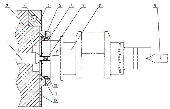
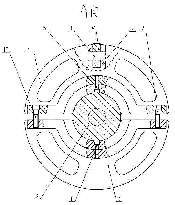
[0011] from figure 1 with figure 2 It can be seen that a crankshaft clamping dial includes a machine tool spindle 2 with a top 1 in the center, an upper shoe seat 4, a lower shoe seat 12, an upper slip 6 and a lower slip 10. A lug 41 is provided, and a pin hole is provided on the lug 41. A lug groove and a pin hole are provided on the outer edge of the end surface of the machine tool spindle 2. The upper tile seat 4 and the lower tile seat 12 are centered on the top 1 of the machine tool spindle. , installed symmetrically up and down on the end face of the machine tool spindle 2, the upper shoe lug 41 is correspondingly installed in the lug groove of the machine tool spindle, and the pin 3 passes through the pin hole on the lug 41 and the pin holes on both sides of the lug groove, The upper shoe seat 4 and the machine tool spindle 1 are connected and fixed by the pin 3; the two sides of the upper shoe seat 4 and the lower shoe seat 12 are connected together by the connecting...


PUM


Abstract

The invention relates to a driver plate for clamping a crank shaft, which comprises a lathe main shaft provided with a finial in the center, an upper tilting fillet, a lower tilting fillet, an upper clamping tile and a lower clamping tile, wherein a lug is arranged on the upper tilting fillet; a pin hole is formed in the lug; a lug groove and a pin hole are formed in the outer edge of the end face of the lathe main shaft; the upper tilting fillet and the lower tilting fillet take the finial as the centers, and are mounted on the end face of the lathe main shaft in an up-and-down symmetrical manner; the upper tilting fillet lug is correspondingly mounted in the lug groove of the lathe main shaft, and is connected and fixed through a pin; the upper tilting fillet and the lower tilting fillet are connected through connecting bolts; the upper clamping tile and the lower clamping tile are mounted in the upper tilting fillet and the lower tilting fillet respectively; the large end of the crank shaft is mounted between the upper clamping tile and the lower clamping tile, and the crank shaft can be clamped by tightening the connecting bolts between the upper tilting fillet and the lower tilting fillet; when the lathe main shaft rotates, a feeding device of a lathe can be operated to process a workpiece. The driver plate has a reasonable structure, is convenient to operate, safe and reliable to clamp, and applicable to the assembly of different shaft diameter size, therefore, the driver plate is an ideal driver plate for clamping the crank shaft.

Description

technical field [0001] The invention relates to a clamping device for shaft parts, in particular to a crankshaft clamping dial. Background technique [0002] We know that when processing shaft workpieces on lathes or grinders, the center holes at both ends of the workpiece are mostly used to tighten the top axially. This device is more suitable for small and medium-sized shaft parts. For larger crankshafts, this method not only has poor safety and reliability, but also has a small clamping range, which cannot meet the processing needs of crankshafts with different shaft diameters. Contents of the invention [0003] The technical problem to be solved by the present invention is to overcome the deficiencies of the above-mentioned prior art, and provide a crankshaft clamping dial with reasonable structure, simple manufacture, convenient operation, safe and reliable clamping, and suitable for assembly of different shaft diameters. [0004] The technical solution adopted by t...

Claims


Application Information

Patent Timeline
Patent Type & Authority Applications(China)
IPC IPC(8): B23Q3/12
CPCB23B23/00
Inventor 丛建臣宋军鹏宫新波宋文友
Owner TIANRUN IND TECH CO LTD
Why Eureka
Try Eureka