
Steel tower self-lifting installation method

An installation method and self-elevating technology, which is applied in the direction of erecting/assembling bridges, bridge parts, bridges, etc., can solve the problems of inconvenient operation and many auxiliary facilities for installation, and achieve simple facilities, small operating height and ensure the quality of tailor welding Effect

Active Publication Date: 2010-07-07
1ST ENG OF CHINA ZHONGTIE MAJORBRIDGE GROUP
View PDF4 Cites 0 Cited by
  • Summary
  • Abstract
  • Description
  • Claims
  • Application Information

AI Technical Summary

Problems solved by technology

[0002] Steel towers are mainly used in bridge projects such as cable-stayed bridges. In the existing vertical rotation construction methods, it is generally necessary to set up a huge lifting tower, and a strong foundation is set under the lifting tower. In order to improve the stability of the tower, it is often necessary to The anchor cable structure is set, and the lifting equipment is generally placed on the top of the tower. During the vertical rotation of the steel tower, there are many installation auxiliary facilities invested in the construction and the operation is inconvenient.

Method used


Image

  • Steel tower self-lifting installation method
  • Steel tower self-lifting installation method
  • Steel tower self-lifting installation method

Examples


Embodiment Construction

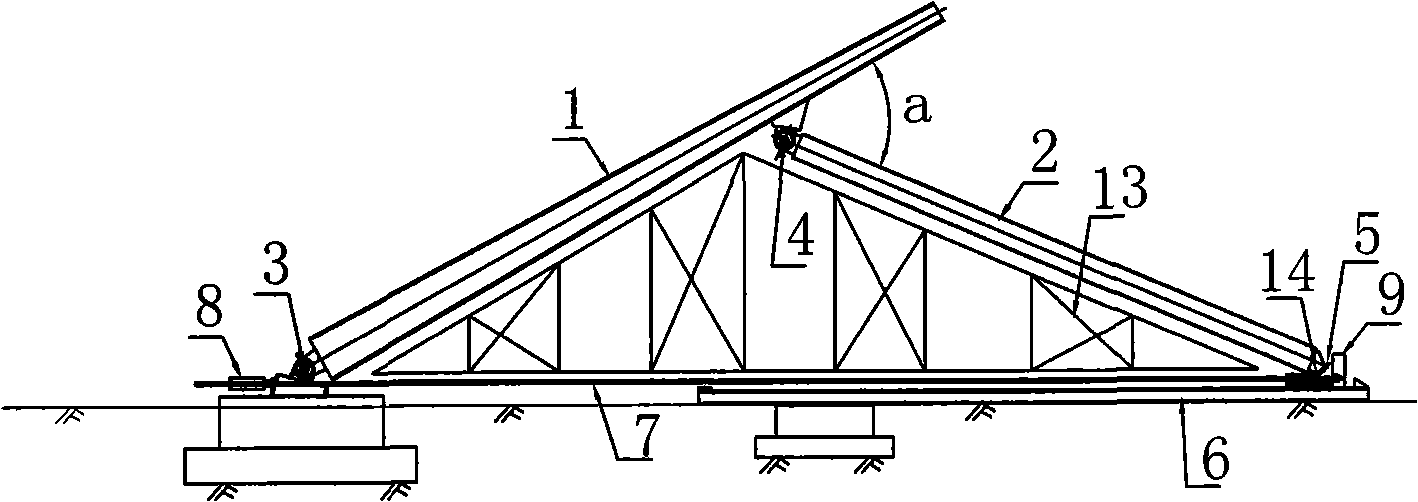
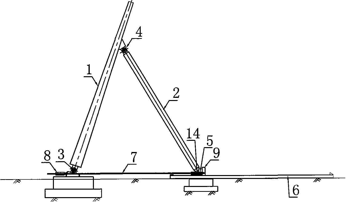
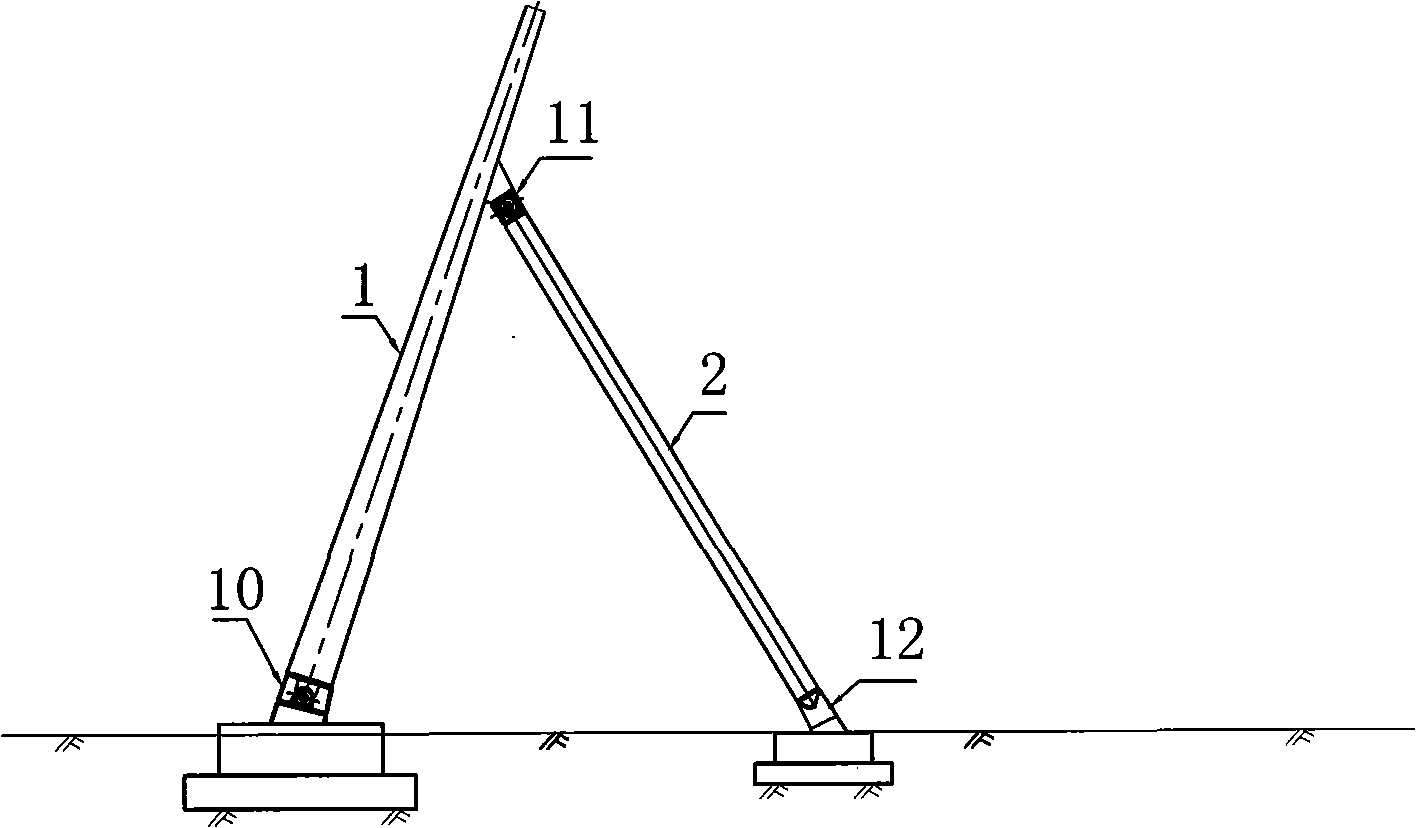
[0013] Such as figure 1 As shown, taking the construction of a "herringbone"-shaped steel tower as an example: first, set up a simple temporary support 13 under the steel tower 1 and the inclined legs 2, and make a certain angle a between the steel tower 1 and the inclined legs 2, and the steel tower 1 Can not overlap with the inclined leg 2 in parallel to avoid self-elevation difficulties, and then use the lifting equipment on the ground to tailor weld the steel tower 1 and the inclined leg 2 on the temporary support 13. Install the hinge 3 at the bottom of the steel tower; install the hinge 4 between the steel tower 1 and the inclined leg 2 (for the single-column steel tower, the auxiliary leg 2 can be set on the main body of the steel tower 1); install the slideway 6; install the inclined leg 2 Bottom ball boot 14 (or hinge) and slide plate 5, slide plate 5 is positioned on slideway 6; Then prestressed steel strand 7 is set between steel tower base and auxiliary leg bottom,...


PUM


Abstract

The invention discloses a steel tower self elevating installation method, wherein a rotating hinge is arranged on the bottom portion of a steel tower main body, an auxiliary leg is hinged on the steel tower main body, after the steel tower main body and the auxiliary leg are welded on an assembling support on site, a tension system is arranged between a base of the steel tower and the bottom portion of the auxiliary leg, the steel tower is achieved to vertically rotate and lift to a scheduled position through tensioning the tension system, and then a fixed structure on the rotating hinge which is arranged on the bottom portion of the steel tower is arranged. The steel tower self elevating installation method has the advantages that: 1, the rotating hinge is arranged between the steel tower and the auxiliary leg and the steel tower and the base, the auxiliary leg of a herringbone steel tower is capable of directly using an inclined leg of the steel tower, thereby the steel tower and the auxiliary leg are convenient to be welded near the ground by lifting equipment on the ground, and the welding quality is easy to be guaranteed. 2, A prestressing tendon is arranged between the base of steel tower and the bottom portion of the auxiliary leg and supplies power for the vertical rotating of the steel tower through the tension of a jack, the steel tower lifts to the scheduled position by itself, the facilities are simple, the operation height is low, and the operation is convenient.

Description

technical field [0001] The invention relates to a method for installing a bridge steel tower. Background technique [0002] Steel towers are mainly used in bridge projects such as cable-stayed bridges. In the existing vertical rotation construction methods, it is generally necessary to set up a huge lifting tower, and a strong foundation is set under the lifting tower. In order to improve the stability of the tower, it is often necessary to The anchor cable structure is set, and the lifting equipment is generally placed on the top of the tower. During the vertical rotation of the steel tower, there are many installation auxiliary facilities invested in the construction and the operation is inconvenient. Contents of the invention [0003] The purpose of the invention is to provide a new bridge steel tower installation method. [0004] In order to achieve the above object, the present invention adopts the following technical scheme: a steel tower self-elevating installation...

Claims


Application Information

Patent Timeline
Patent Type & Authority Patents(China)
IPC IPC(8): E01D21/00E01D19/14
Inventor 冯广胜李艳哲周功建李富仓郭荣春
Owner 1ST ENG OF CHINA ZHONGTIE MAJORBRIDGE GROUP
Learn More