Novel gantry crane plane movable parking equipment

A technology of gantry cranes and parking equipment, which is applied in the direction of buildings, building types, buildings, etc. where cars are parked, and can solve the problems of low garage utilization and high cost

Active Publication Date: 2010-06-09
江苏利创新能源有限公司
View PDF3 Cites 0 Cited by
  • Summary
  • Abstract
  • Description
  • Claims
  • Application Information

AI Technical Summary

Problems solved by technology

However, a gantry crane can only arrange parking spaces on one floor, and a gantry crane can only serve the vehicle access and handover process on the same floor, so the cost of the overall parking equipment is high, and the utilization rate of the garage is low

Method used


Image

  • Novel gantry crane plane movable parking equipment
  • Novel gantry crane plane movable parking equipment
  • Novel gantry crane plane movable parking equipment

Examples


Embodiment 1

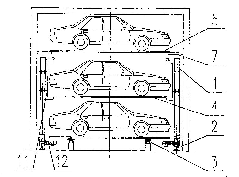
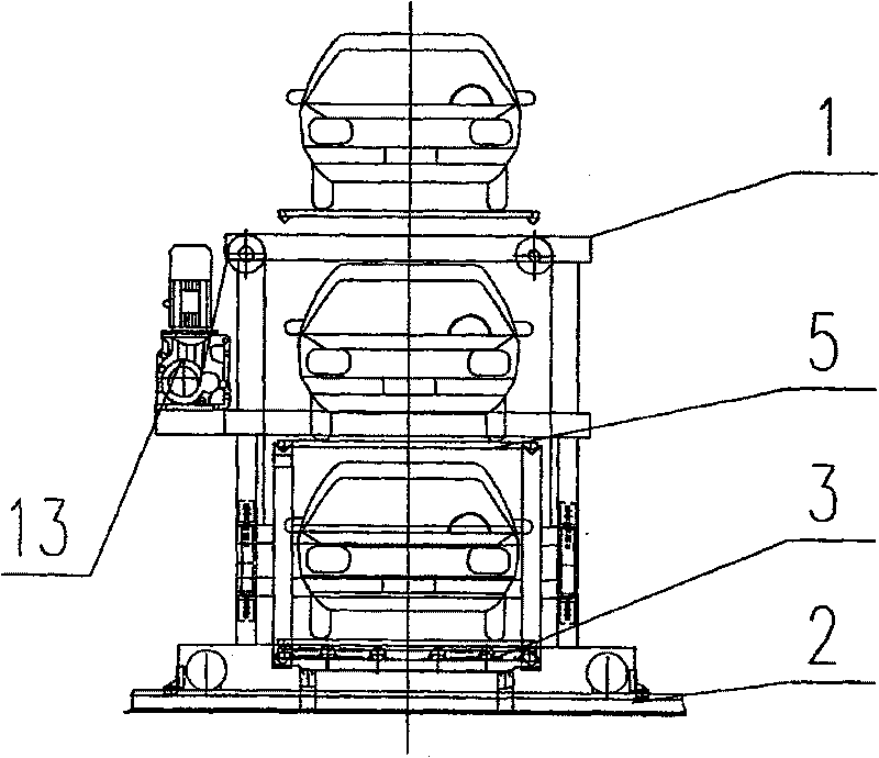
[0020] see Figure 1-3 , The novel gantry crane planar mobile parking equipment that the present invention relates to mainly consists of an upper car-carrying plate 5, a lower car-carrying plate 4, a raceway 3, a track 2 and a gantry crane carrier 1. The parking equipment has two upper and lower floors, the upper vehicle-carrying plate 5 rests on the upper fixed bracket 7 of the parking equipment, the lower vehicle-carrying plate 4 rests on the raceway 3, and there are two rails 2, Two rails 2 are arranged in parallel on the left and right sides of the raceway 3 .

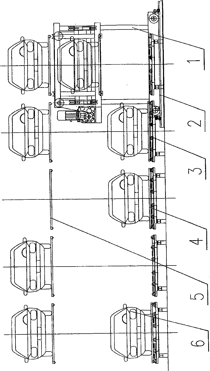
[0021] see Figure 4-5 , the gantry crane carrier 1 has one, and the gantry crane carrier 1 is mainly composed of a gantry frame, an access exchange device, a lifting drive system 1.12 and a walking drive system. The gantry frame is mainly composed of columns 1.1, upper longitudinal beams 1.4, middle longitudinal beams 1.5, upper beams 1.13, middle beams 1.14 and lower beams 1.15, which are the structural main bo...

Embodiment 2

[0025] see Figure 8 , Figure 8 It is a schematic diagram of the second elevation of the embodiment of the present invention. In this embodiment, the lower vehicle-carrying board bracket 10 is used to replace the raceway 3 in Embodiment 1. Supporting leg 9 can be made identical with upper strata car-loading plate 5 external structure, as Figure 9 . Both the upper vehicle loading plate 5 and the lower floor vehicle loading plate 4 are composed of a vehicle loading plate body 8 and supporting legs 9 . The lower floor's vehicle-carrying board 4 directly rests on the lower floor's car-loading board bracket 10 .

[0026] Combine below Figure 10 (a), (b), (c) illustrate the pick-up process:

[0027] When the vehicle 6 in the No. 2 parking space on the lower floor is to be removed, a pick-up signal for the No. 2 parking space is given. After the gantry crane carrier 1 automatically moves horizontally to the appropriate position of the No. 2 parking space, the access switchin...


PUM


Abstract

The present invention relates to a novel door type crane planar movement parking device, comprising an upper layer vehicle bearing plate (5), a lower layer vehicle bearing plate (4), a raceway (3) ora bracket (10), tracks (2) and a door type crane carrier (1), wherein the lower layer vehicle bearing plate (4) is laid on the raceway (3) or the bracket (10); the present invention is provided with two tracks (2) arranged on the left side and the right side of the raceway (3) in parallel; one door type crane carrier (1) is provided, comprising a gantry type framework, an access exchange device, alifting drive system (1.12) and a walking drive system; the access exchange device is divided into two half parts which are respectively arranged on the left side and the right side of the gantry type framework in symmetrical arrangement; each half access exchange device comprises a guide frame (1.9), an upper positioning access claw (1.2), a lower positioning access claw (1.3) and idler pulleys(1.10). Due to the present invention, one door type crane of can be provided with two layers of parking stalls and can serve the two-layer vehicle access handover process of different layers, which can effectively raise the number of parking stalls, improve the vehicle holding density of mechanical three-dimensional parking equipment and shorten vehicle access time.

Description

technical field [0001] The invention relates to a mechanical three-dimensional parking equipment, in particular to a plane mobile parking equipment. Background technique [0002] At present, in the plane mobile parking equipment, there are mainly two ways to transport vehicles. One is to use a transport trolley as a carrier to transport vehicles in the horizontal direction. This transportation method is suitable for occasions with large garage sizes and widths; the other In order to use a gantry crane as a carrier to move the vehicle in the horizontal direction, this handling method is suitable for occasions where the size and width of the garage is small. However, a gantry crane can only arrange parking spaces on one floor, and a gantry crane can only serve the vehicle access and handover process on the same floor, so the cost of the overall parking equipment is high, and the utilization rate of the garage is low. Contents of the invention [0003] The object of the pres...

Claims


Application Information

Patent Timeline
Patent Type & Authority Patents(China)
IPC IPC(8): E04H6/18
Inventor 许明金
Owner 江苏利创新能源有限公司
Why Eureka
Try Eureka