
A plate-type tandem mechanical parking equipment with a chain-driven rotary center lift

A mechanical parking and chain drive technology, which is applied to the buildings, building types, buildings, etc. where cars are parked, can solve the problems of long access time, increased garage cost, and increased lateral movement, so as to achieve the access time Short, save traverse action, reduce the effect of driving difficulty

Active Publication Date: 2016-04-27
SHANDONG TIANCHEN INTELLIGENT PARKING EQUIPMENT CO LTD
View PDF5 Cites 0 Cited by
  • Summary
  • Abstract
  • Description
  • Claims
  • Application Information

AI Technical Summary

Problems solved by technology

This kind of garage has the following disadvantages: 1. The lift occupies all the parking spaces from top to bottom where it is arranged, which reduces the overall parking number of the garage; 2. There is no rotating mechanism. High level requirements for drivers; 3. The carriers on each floor are independent of each other and cannot be shared; even if there are fewer parking spaces on each floor of this garage structure, carriers must be installed on each floor, which increases the cost of the garage; 4. Increase The horizontal movement must be realized in multiple steps according to the steps. It takes a long time to access the car, which reduces the efficiency of the car access. In the existing three-dimensional garage, it takes about 2 minutes to access the vehicle in the nearest parking space. It can take up to half an hour to pick up the vehicles in the last few parking spaces
[0006]The structure of lift-and-slide parking garage is simple, and it is the most convenient to access cars. However, due to the limitation of the number of floors, the scale is limited and the capacity is small; The capacity, volume and access speed of the library cannot be balanced at the same time

Method used


Image

  • A plate-type tandem mechanical parking equipment with a chain-driven rotary center lift
  • A plate-type tandem mechanical parking equipment with a chain-driven rotary center lift
  • A plate-type tandem mechanical parking equipment with a chain-driven rotary center lift

Examples


Embodiment Construction

[0035] The present invention will be further described below through non-limiting embodiments and in conjunction with the accompanying drawings.

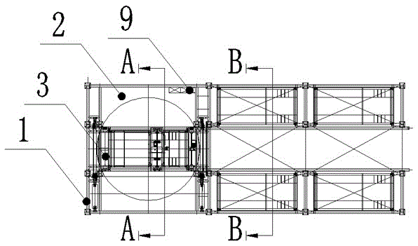
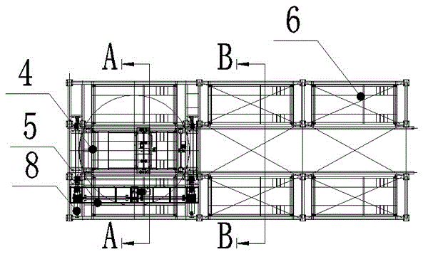
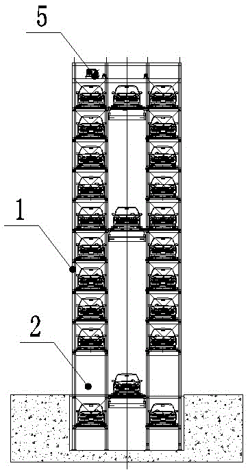
[0036] Such as Figure 1 to Figure 7 As shown, a plate-type tandem mechanical parking device of a chain-driven rotary elevator, the parking garage has 11 floors, 10 floors above the ground, and 1 floor underground, including a steel structure frame 1, an entrance and exit 2, a hoist 5, an elevator 3, and a distribution system. Heavy device 8, carrier 4, access switching mechanism and electrical control system; hoist 5 is set on the top of steel structure frame 1, steel structure frame 1 is composed of 11 parking floors and roadways, parking floors are arranged on both sides of the roadway, The 4 parking spaces on each parking floor are longitudinally arranged into a 2-row plate-type column structure, and each parking space is provided with a vehicle-carrying plate 6, which is accessed synchronously with the vehicle, and the vehicle-...


PUM


Abstract

The invention discloses a plate-type tandem mechanical parking device with a chain-driven rotary center lift. Its hoist is set on the top of the steel structure frame. The steel structure frame is composed of multi-layer parking floors and roadways. The vehicle-carrying plate on the parking space can move horizontally along the parking guide rail on the parking space; the roadway of each parking floor is provided with a fixed guide rail for the carrier to travel longitudinally; The carrier is set on the moving guide rail, and the access and exchange mechanism is set on the carrier; the end of the roadway is provided with an elevator shaft that runs from the bottom floor to the top floor, and the elevator is set in the elevator shaft. The elevator and the entrance and exit are located at the end of the roadway. Occupies any parking space, and saves the lateral movement from the entrance and exit to the roadway, and the time for accessing the car is short. The elevator has a slewing device, and the accessing vehicle can be in and out.

Description

technical field [0001] The invention relates to the technical field of three-dimensional parking equipment, in particular to multi-storey or high-level plane mobile three-dimensional parking equipment. Background technique [0002] With the development of the automobile industry and the improvement of people's living standards, the per capita car ownership in cities continues to increase. However, with the increase of urban population, people's living space is getting smaller and smaller, and there are almost no parking spaces. In order to adapt to parking People began to use a large number of three-dimensional garages to solve the problem of insufficient parking spaces. [0003] In the "Special Equipment Catalog" promulgated by the General Administration of Quality Supervision, Inspection and Quarantine of the People's Republic of China, the three-dimensional garages are divided into nine categories, specifically: lifting and moving, simple lifting, vertical circulation, ho...

Claims


Application Information

Patent Timeline
Patent Type & Authority Patents(China)
IPC IPC(8): E04H6/18E04H6/22E04H6/28
Inventor 申景超刘钊刘健纪汶礼
Owner SHANDONG TIANCHEN INTELLIGENT PARKING EQUIPMENT CO LTD
Learn More