Magnetic drive pump

A magnetic pump and magnetic drive technology, applied in the field of magnetic pumps, can solve the problems of difficult disassembly of threaded parts, consuming man-hours, increasing costs, etc., and achieving the effects of convenient disassembly, cost saving and high reliability

Inactive Publication Date: 2008-08-27
蔡国华
View PDF0 Cites 3 Cited by
  • Summary
  • Abstract
  • Description
  • Claims
  • Application Information

AI Technical Summary

Problems solved by technology

But this method makes it difficult to disassemble the threaded part (8) from the inner magnetic steel (3) when the magnetic pump needs maintenance, and even the whole threaded part (8) can only be sawed off from the pump shaft, and has to replace complete set
It not only consumes man-hours, but also causes a lot of waste and increases costs

Method used


Image

  • Magnetic drive pump
  • Magnetic drive pump

Examples


Embodiment Construction

[0014] The specific embodiment of the present invention is described below in conjunction with accompanying drawing:

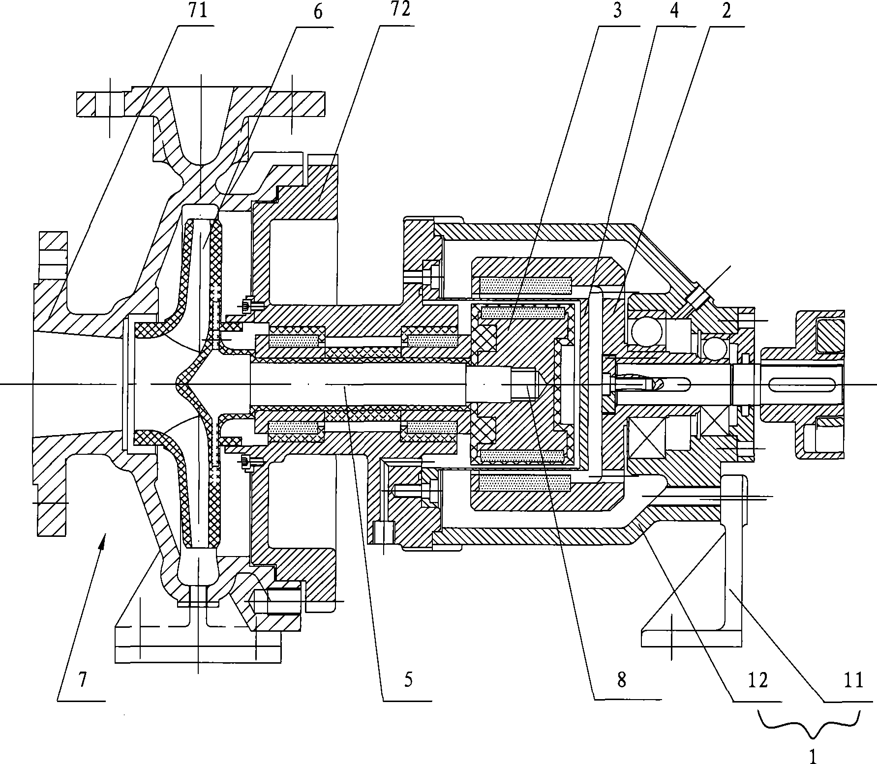
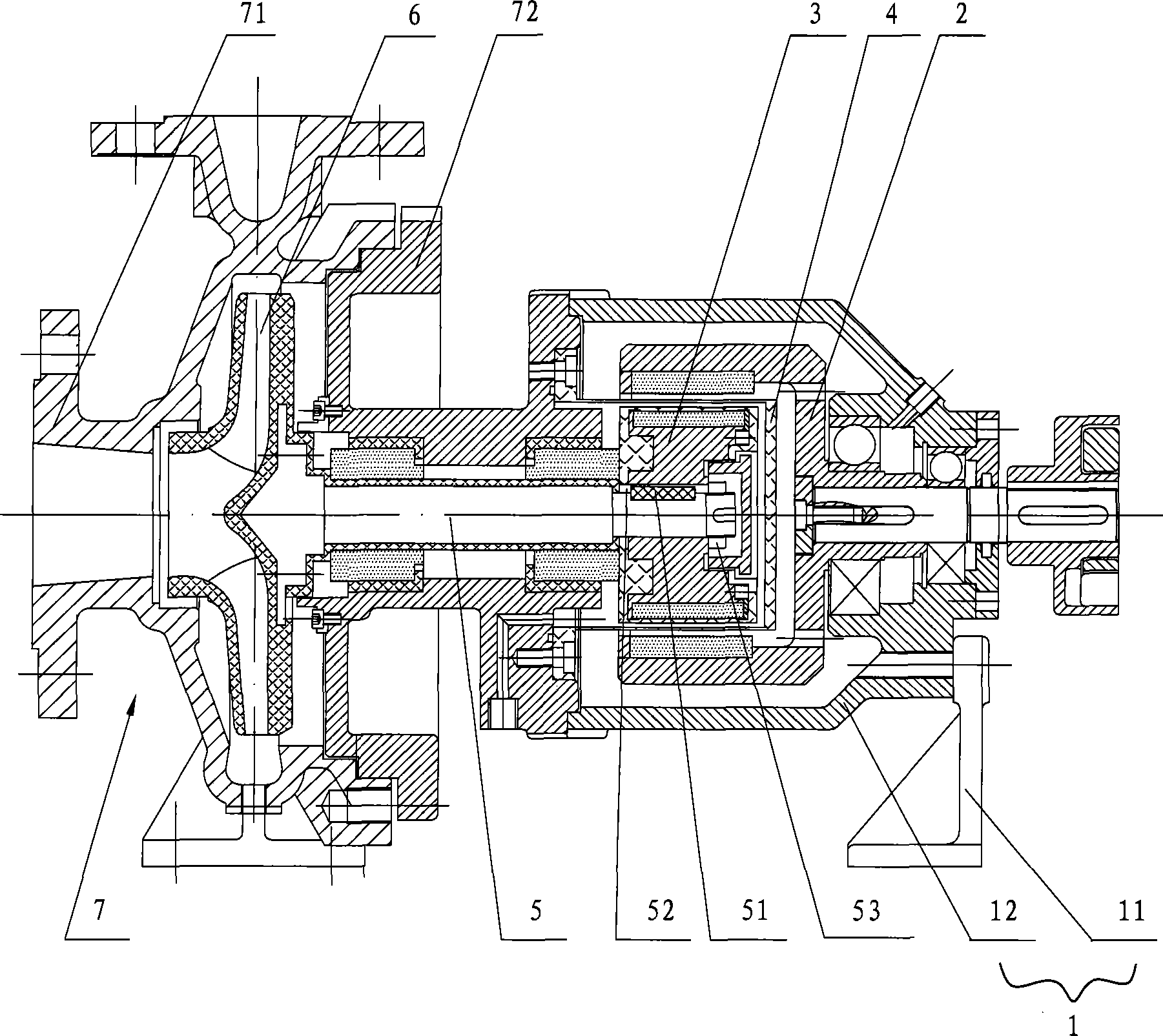
[0015] as attached figure 2 As shown, the magnetic pump implemented according to the present invention includes a bracket 1 composed of a bracket 11 and a suspension 12 fixedly installed on the bracket 11, an outer magnetic steel 2 directly connected with the motor and driven by the motor, and The inner magnetic steel 3 arranged concentrically with the outer magnetic steel 2, the spacer sleeve 4 arranged between the outer magnetic steel 2 and the inner magnetic steel 3, the pump shaft 5 connected with the inner magnetic steel 3 at one end, and the pump shaft 5 installed on the pump shaft The impeller 6 , the pump casing 7 located outside the pump shaft 5 and fixedly connected with the bracket 1 , the sliding bearing 8 and the thrust bearing 9 arranged concentrically with the pump shaft 5 . Wherein, the outer magnet 2 drives the inner magnet 3 to rotate throu...


PUM


Abstract

The invention relates to a magnetic drive pump which comprises a support, a motor, outer magnetic steel driven by the motor, inner magnetic steel arranged concentric to the outer magnetic steel and capable of rotating under the drive of the magnetic force of the outer magnetic steel, an isolation sleeve arranged between the outer magnetic steel and the inner magnetic steel, a pump shaft with one end connected with the inner magnetic steel, impellers arranged on the pump shaft, a pump casing positioned outside the pump shaft and fixed with the support as well as a sliding bearing and a thrust bearing arranged concentric to the pump shaft, wherein the pump shaft is fixed with the inner magnetic steel through a circumferential fixed structure and an axial fixed structure. The mode ensures that the pump shaft does not separate from the inner magnetic steel when the magnetic drive pump is in reverse motion.

Description

technical field [0001] The invention relates to a magnetic pump. Background technique [0002] The magnetic pump in the prior art is as attached figure 1 As shown, the pump shaft (5) of the magnetic pump and the inner magnetic steel (3) are generally connected by threads, as shown in the attached figure 1 As shown, one end of the pump shaft (5) is a threaded portion (8), which is screwed into the inner magnetic steel (3) through thread fit. Since the magnetic pump may reverse during operation, the threaded connection at the end of the pump shaft (5) is loosened, resulting in the separation of the inner magnetic steel (3) from the pump shaft (5). [0003] In order to prevent the disengagement of the thread here, a sealant is usually used to seal it in the prior art. But this method makes it difficult to disassemble the threaded part (8) from the inner magnetic steel (3) when the magnetic pump needs maintenance, and even the whole threaded part (8) can only be sawed off fro...

Claims


Application Information

Patent Timeline
IPC IPC(8): F04D29/04F04D29/05F04D29/00F04D29/60
Inventor 蔡国华
Owner 蔡国华
Why Eureka
Try Eureka