Focusing lens for LED

A focusing lens and lens part technology, applied in the field of focusing lenses, can solve problems such as functional limitations

Inactive Publication Date: 2008-08-27
SEKONIX
View PDF0 Cites 25 Cited by
  • Summary
  • Abstract
  • Description
  • Claims
  • Application Information

AI Technical Summary

Problems solved by technology

Therefore, for illuminating a local area from a distance, the function of the conventional focusing lens 10 has its limit.

Method used


Image

  • Focusing lens for LED
  • Focusing lens for LED
  • Focusing lens for LED

Examples


Embodiment Construction

[0018] Hereinafter, embodiments of the present invention will be described in detail with reference to the accompanying drawings.

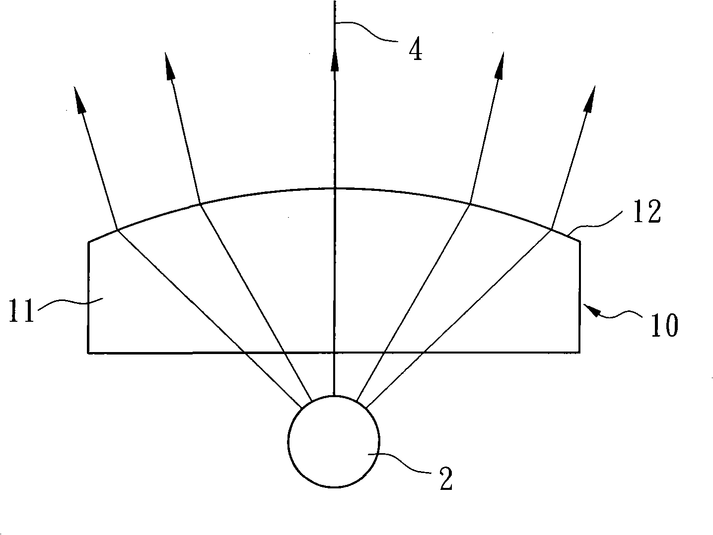
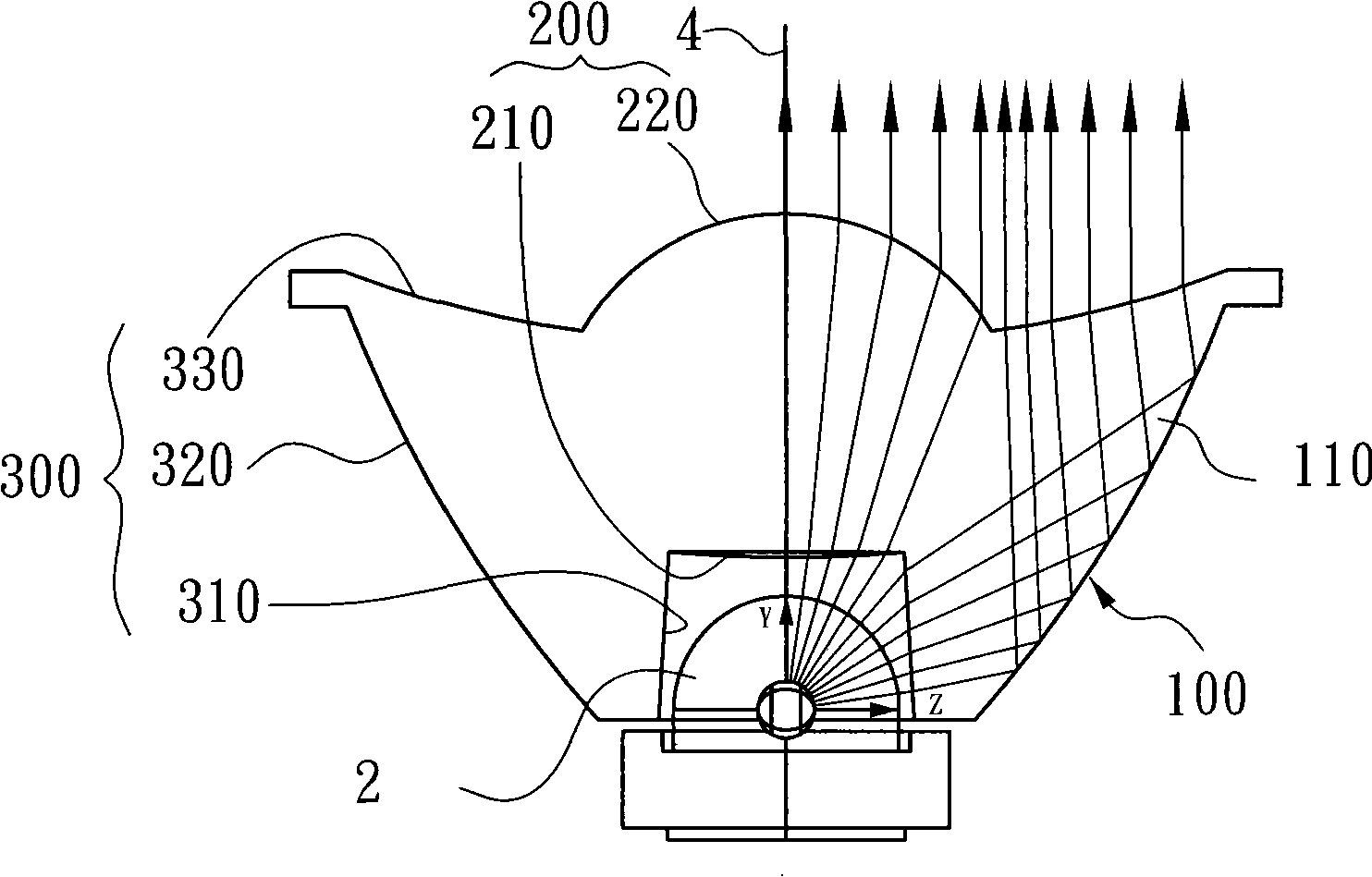
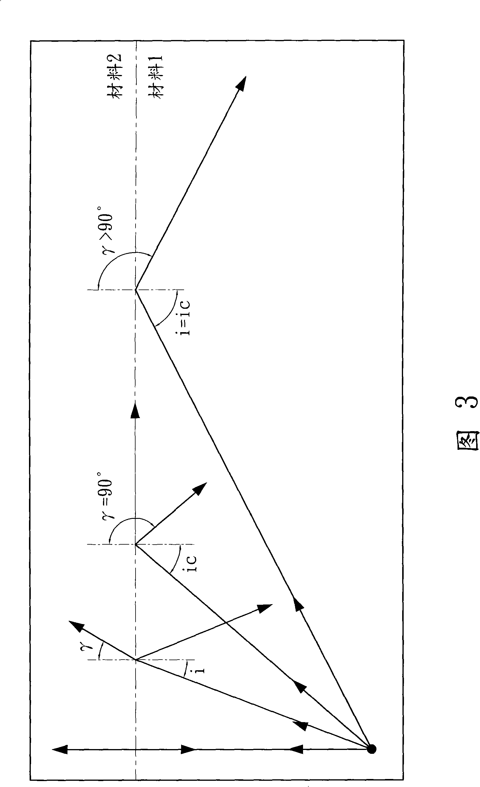
[0019] figure 2 And FIG. 3 is an explanatory diagram of the focusing lens 100 of the LED 2 of the present invention.

[0020] refer to figure 2 , the focusing lens 100 is used to concentrate the light emitted from the LED to make it directional. The focusing lens 100 includes a transparent body 110 . The main body 110 includes a first lens part 200 and a second lens part 300 . The first lens portion 200 is formed by a convex aspherical lens located in the middle of the body 110 . The second non-lens part 300 covers the edge part of the first lens part 200 .

[0021] The first lens part 200 includes first and second aspheric lens surfaces 210 and 220 . The first and second aspherical lens surfaces 210 and 220 are convex shapes with different sizes, and are located on mutually symmetrical planes, ie, upper and lower surfaces.

[0022] The s...


PUM


Abstract

A focusing lens for an LED, which concentrates light emitted from the LED so as to have directionality parallel to an optic axis, comprises: a transparent body; a first lens part formed in the body; and a second lens part covering the first lens part, and wherein the first lens part comprises: a first and second aspheric lens surfaces which are convex with different sizes and form on plat surfaces symmetric with each other. The second lens comprises a plane of incidence formed to protrude from an outer circumference of the first aspheric lens surface, the plane of incidence into which the LED is inserted and which is configured to allow the light emitted from the LED to be incident and refracted; a plane of reflection formed to have a convex curved surface which extend and slopes to be progressive wider from the plane of incidence towards the second aspheric lens surface, the plane of reflection which is configured to allow the light emitted from the LED to be totally reflected; and a plane of emission formed to have a concave curved surface which extends and slopes from the plane of reflection towards the second aspheric lens surface, the plane of emission which is configured to allow the light emitted from the LED to be refracted and emitted as light being parallel to the optic axis.

Description

technical field [0001] The present invention relates to an LED focusing lens, and more specifically relates to an LED focusing lens, which is used to control the radiation angle of the LED to illuminate a remote local area. Background technique [0002] Generally, LEDs radiate low illumination light, that is, LEDs radiate light at a large angle, due to the characteristics of LEDs. Therefore, LEDs can only be used to illuminate large areas, or for close-range lighting. [0003] Due to the characteristics of the LED, its radiation angle is very large, if it is used to illuminate a long-distance local area, it will diffuse and cannot effectively use the emitted light. [0004] In order to reduce the problem of uncovering, it has been figure 1 The focusing lens shown was developed to focus the light emitted by the LED. [0005] like figure 1 As shown, a conventional focusing lens 10 is placed at the position where the LED emits light. [0006] The entire body 11 of the focu...

Claims


Application Information

Patent Timeline
Patent Type & Authority Applications(China)
IPC IPC(8): G02B3/02G02B3/00G02B27/00
CPCG02B19/0061G02B19/0028H01L33/58G02B3/02F21Y2101/02H01L33/60G02B17/0868F21V5/04F21Y2115/10G02B27/30
Inventor 金井贺黄尚富李希俊
Owner SEKONIX
Why Eureka
Try Eureka