Direct-current power supply slow startup control circuit
A technology for controlling circuits and DC power supplies, applied to electrical components, output power conversion devices, etc., can solve problems such as ringing interference, output voltage reduction, and fuse blown
- Summary
- Abstract
- Description
- Claims
- Application Information
AI Technical Summary
Problems solved by technology
Method used
Image
Examples
Embodiment Construction
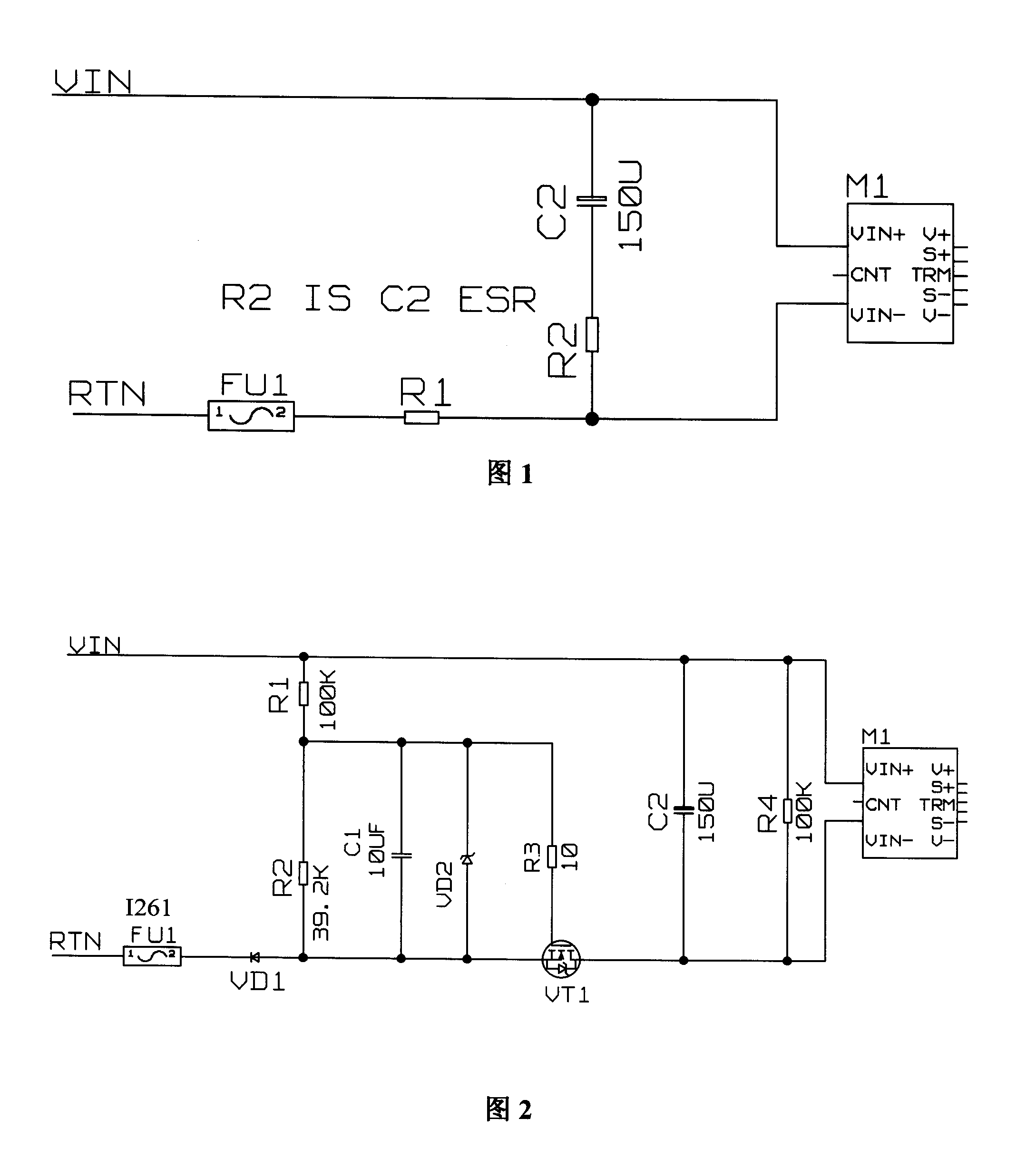
[0035] As shown in Figure 2, the first kind of slow start that the present invention adopts realizes the circuit:
[0036] (1) Circuit structure
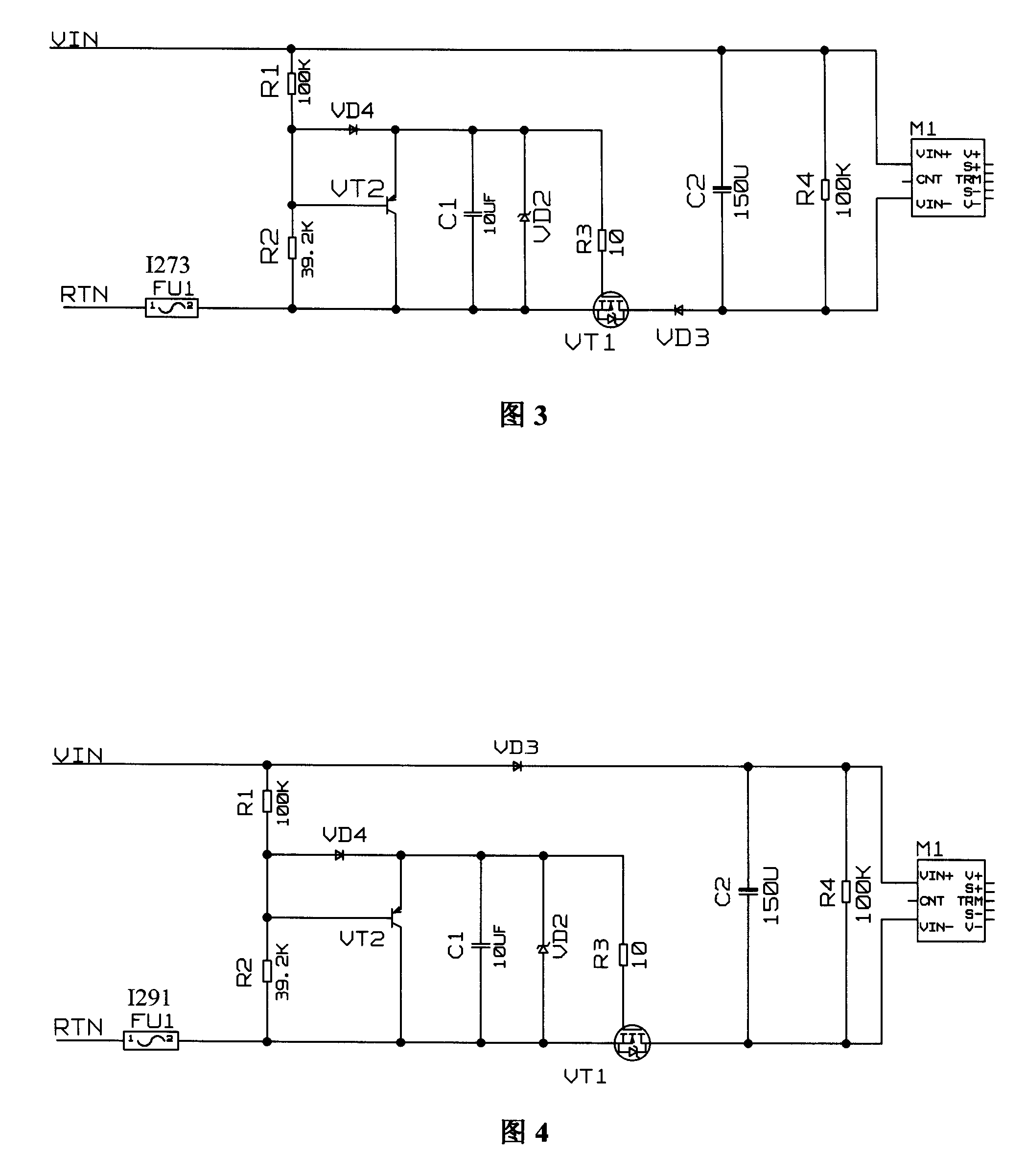
[0037] The core part of the circuit includes a transistor that controls the inrush current. This circuit uses an N-channel insulated gate field effect transistor VT1. The related control circuit includes voltage dividing resistors R1 and R2, connected to the input voltage terminal, and a capacitor C1 connected in parallel with R2. , and connected together at the gate-source level of VT1. VD1 is an input voltage anti-reverse diode. It is only used for anti-reverse connection and does not participate in slow start control. In addition, FU1 is a circuit thermal fuse, VD2 is a Zener voltage regulator, and R3 is a gate resistor, which is an accessory device of the slow start circuit. C2 is the input capacitor of the DC power module M1, and R4 is the discharge resistor of C2.
[0038] (2) Working principle
[0039] After power-on, th...
PUM
 Abstract
Description
Claims
Application Information
 - R&D
- Intellectual Property
- Life Sciences
- Materials
- Tech Scout
- Unparalleled Data Quality
- Higher Quality Content
- 60% Fewer Hallucinations
Browse by: Latest US Patents, China's latest patents, Technical Efficacy Thesaurus, Application Domain, Technology Topic, Popular Technical Reports.
© 2025 PatSnap. All rights reserved.Legal|Privacy policy|Modern Slavery Act Transparency Statement|Sitemap|About US| Contact US: help@patsnap.com


