
System and method for multi-mode capable of reconfiguring fan antenna

A sector antenna, sector angle technology, applied in the direction of antenna, antenna support/mounting device, electrical components, etc., can solve the problems of polarization mismatch and so on

Inactive Publication Date: 2008-08-27
TELEFON AB LM ERICSSON (PUBL)
View PDF0 Cites 0 Cited by
  • Summary
  • Abstract
  • Description
  • Claims
  • Application Information

AI Technical Summary

Problems solved by technology

Therefore, problems arise when a signal needs to be radiated over an area with a polarization that does not match that of the sectored antenna

Method used


Image

  • System and method for multi-mode capable of reconfiguring fan antenna
  • System and method for multi-mode capable of reconfiguring fan antenna
  • System and method for multi-mode capable of reconfiguring fan antenna

Examples


Embodiment Construction

[0022] As shown in the figures for purposes of illustration, the present invention may be embodied in a system and method for radiating a beam from a sectored antenna in one of a plurality of directions. These directions include at least one defined sector. Embodiments of the present invention allow a sectored antenna to be configured during or after its assembly to enable one of multiple radiating arrays to radiate over one of multiple sectors where the sectored antenna has been activated to operate at any given radiates on a single sector, and where this sectored antenna can be reconfigured to radiate on an alternate sector.

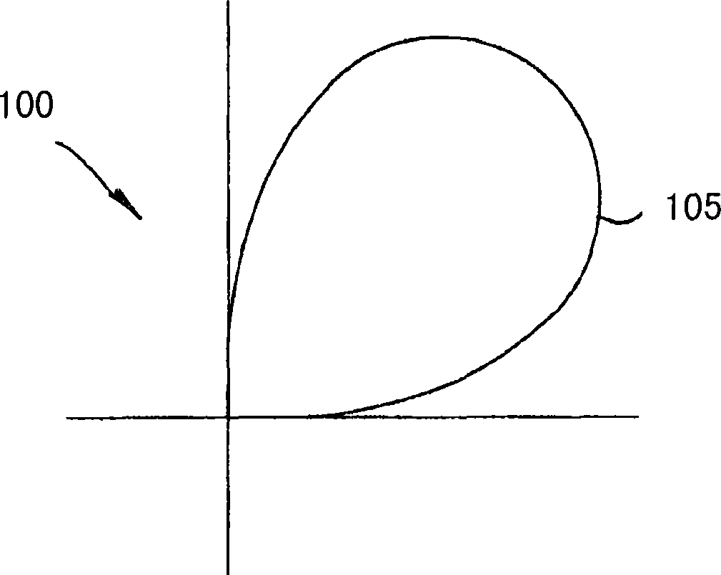
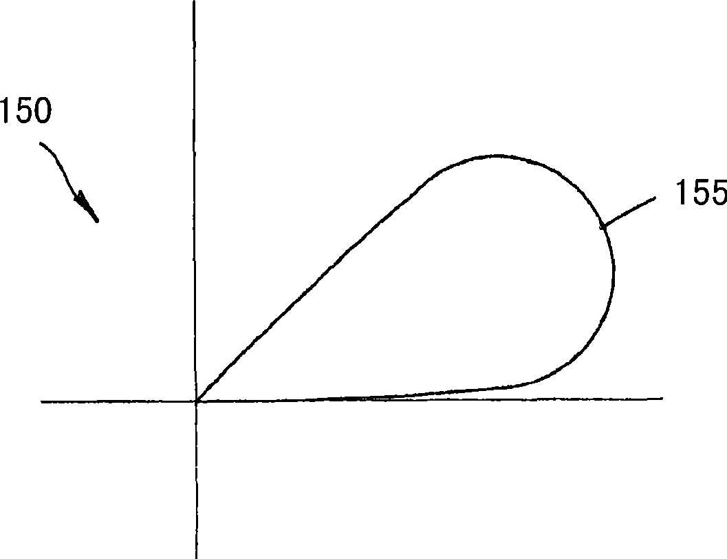
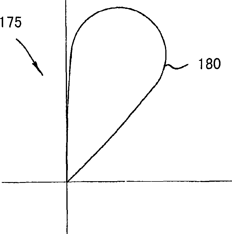
[0023] As a brief overview, Figure 1a is a simplified azimuth diagram 100 depicting a typical 90 degree aperture angle corresponding to a sector 105 into which a sectored antenna can radiate in accordance with an embodiment of the present invention. An azimuth diagram typically depicts the antenna radiation pattern when looking down from directly abo...


PUM


Abstract

Systems and methods for configuring a single sector antenna capable of operating in multiple modes and comprising a plurality of radiating arrays to radiate over a sector area at a polarization by activating a single radiating array. An enabler activates a single radiating array in a single-unit sector antenna that comprises multiple radiating arrays to allow the sector antenna to operate in the desired mode without interference from additional active radiating arrays, the sector antenna being capable of reconfiguration without unit replacement or system losses to operate in a different mode.

Description

technical field [0001] The present invention relates generally to sector antennas, and more particularly to systems and methods for configurable sector antennas having the ability to radiate at one of a plurality of sector angles based on the characteristics of an effective radiating array to cover multiple A plurality of radiation arrays in a sector in a sector area. Background technique [0002] Antennas are electrical devices that transmit or receive signals. More specifically, the antenna acts as a port through which radio frequency (RF) energy is radiated to or received from the outside world. Common antennas are omnidirectional antennas. An omnidirectional antenna radiates in all directions, essentially in a 360-degree pattern. However, such antennas are not an effective solution to the problem of requiring more directivity or focusing of the radiation. A single robust antenna capable of focusing radiated power on one of several specific areas is ideal, partly beca...

Claims


Application Information

Patent Timeline
IPC IPC(8): H01Q1/24H01Q25/00
Inventor G·马西尼
Owner TELEFON AB LM ERICSSON (PUBL)
Learn More