Lifting device for shift carrying

A lifting device and transfer technology, applied in the direction of lifting device, lifting frame, transportation and packaging, etc., can solve the problems of shortening the installation or moving construction period, time-consuming, inability to adjust the direction and the micro-adjustment of the up and down direction, etc., to shorten the installation or the effect of the relocation period

Active Publication Date: 2012-07-04
NAKANISHI METAL WORKS CO LTD
View PDF2 Cites 0 Cited by
  • Summary
  • Abstract
  • Description
  • Claims
  • Application Information

AI Technical Summary

Problems solved by technology

[0006] In the schemes of Patent Documents 1 and 2, since the column length (pillar height) above the head is required, it is easy to interfere with other equipment in the factory in the assembled state, especially when moving heavy objects such as automobile bodies. In the case of loading, it is difficult to shorten the installation or relocation period and operate early because it requires on-site assembly and on-site installation of auxiliary beams, cantilevers, inspection platforms, and ladders, etc., and requires more man-hours for installation and relocation. needs
[0007] Moreover, according to the proposal of Patent Document 1, after the stand is fixed on the ground with anchor bolts, fine adjustments in the horizontal direction and in the vertical direction cannot be performed. Spend time
[0008] Moreover, according to the proposal of Patent Document 2, the wheels and the adjuster are installed under the feet of the base, so the adjuster can be protruded after being moved by the wheels to install the device on the ground, but since the direction in the horizontal plane and the up and down Fine adjustment of the direction, so from this point of view, the adjustment work at the time of installation and relocation also takes time

Method used


Image

  • Lifting device for shift carrying
  • Lifting device for shift carrying
  • Lifting device for shift carrying

Examples


Embodiment Construction

[0028] Embodiments of the present invention will be described in detail below with reference to the accompanying drawings. The present invention is not limited to the forms shown in the drawings, but includes all implementations that satisfy the conditions described in the protection scope of the patent application.

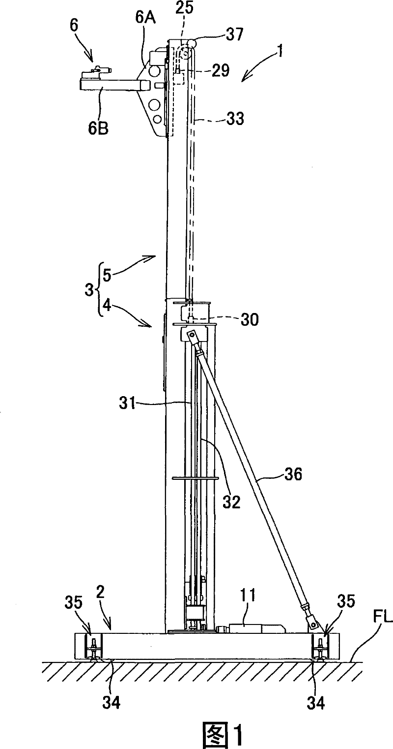
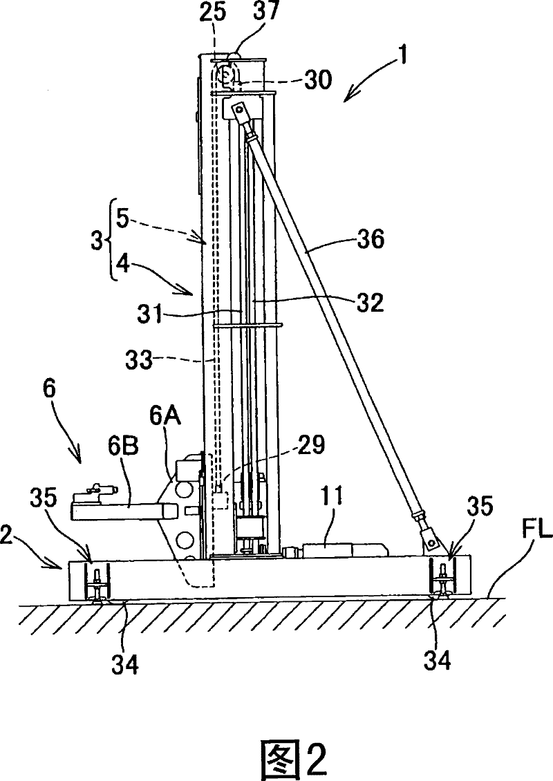
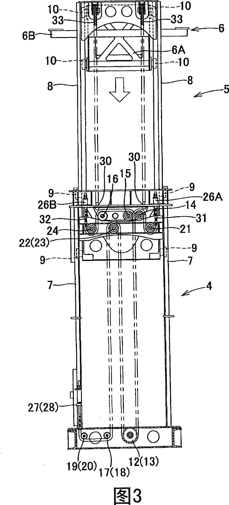
[0029] In addition, in this specification, the direction in which the support arm 6B extends from the bracket 6A of the workpiece supporting tool 6 is referred to as the front, and the left and right facing forward are referred to as the left and right. figure 1 and figure 2 It is a left side view showing the transfer elevating device 1 according to the embodiment of the present invention, figure 1 Indicates that the lifting column 5 is in a high position state, figure 2 It shows the state that the elevating column 5 is in the low position. image 3 and Figure 4 is a partially cutaway rear view for illustration of the chain linkage mechanism, image 3 I...


PUM


Abstract

The invention provides an elevating gear for movement, which is capable of shortening field installation or movement period, and of bringing forward running. The elevating gear comprises a rack (2) fixed on the floor (FL); and a plurality of struts (3) stretched upwards and downward, each of which is composed of a fixing strut (4) extending upwards and a lifting strut (4) sliding upwards and downward relative to the fixing strut (4). By a drive unit, the struts are stretched and a workpiece support tool (6) of the lifting strut (5) is lifted, thus realizing movement between transporters (C1, C2) having different heights. Since the whole height is lower than a lift when the struts (3) are contacted, the elevating gear can not interfere with other apparatuses (FR) even if moved in the state. According to the invention, an elevating gear (1) for movement is assembled and adjusted in a manufacture factory and then delivered, and is installed in field.

Description

technical field [0001] The present invention relates to an elevating device for transfer, which transfers between conveyors having height differences by raising and lowering a workpiece support tool supported by a pillar by a drive device. Background technique [0002] As an existing lifting device for transfer, there are devices such as the following: For example, as described in Patent Document 1, a pair of sprockets are arranged above and below the pillar, the rotation axes of the pair of sprockets are horizontal and parallel to each other, and An endless chain driven by a motor is wound around the wheel, and one of the base end portion and the middle portion of the length of the arm provided with the workpiece supporting tool at the movable end is an elevating member that can slide freely only in the up and down direction with respect to the above-mentioned support. connected, and another passing shaft is connected to the above-mentioned endless chain, as the path of the...

Claims


Application Information

Patent Timeline
Patent Type & Authority Patents(China)
IPC IPC(8): B65G47/52B66F7/00B66F1/00B62D65/18
Inventor 冈崎吉洋
Owner NAKANISHI METAL WORKS CO LTD
Why Eureka
Try Eureka