Method for deducing initial magnetic pole position of permanent magnet synchronous motor

A magnetic pole position and permanent magnet synchronization technology, which is applied in the direction of motor generator control, electromechanical transmission control, electronic commutation motor control, etc., can solve the problem of easy oscillation of the addition and subtraction angle, the inability to obtain the size of the motor shaft end load, and the inability to guarantee the motor Start comfort and other issues, to achieve the effect of smooth start

Active Publication Date: 2008-09-03
NINGBO HONGDA ELEVATOR
View PDF1 Cites 25 Cited by
  • Summary
  • Abstract
  • Description
  • Claims
  • Application Information

AI Technical Summary

Problems solved by technology

[0004] However, the applicant found that the inference method adopted by the above-mentioned invention needs to know the accurate motor inductance in advance, otherwise the sign of ΔU will be judged wrongly, so that it is easy to oscillate when adding and subtracting angles; and when ΔU tends to zero, it will be near the zero value Oscillation, its sign changes more obviously, resulting in a large acceleration change when the motor starts, so that the angle acquisition is not easy to converge, and the comfort of the motor startup cannot be guaranteed; moreover, the load on the motor shaft end cannot be obtained by using this inference method

Method used


Image

  • Method for deducing initial magnetic pole position of permanent magnet synchronous motor
  • Method for deducing initial magnetic pole position of permanent magnet synchronous motor
  • Method for deducing initial magnetic pole position of permanent magnet synchronous motor

Examples


Embodiment Construction

[0019] The method for inferring the initial magnetic pole position of the permanent magnet synchronous motor of the present invention will be further described below in conjunction with the accompanying drawings and specific embodiments:

[0020] Such as Figure 11 Shown, the present invention mainly comprises following three steps:

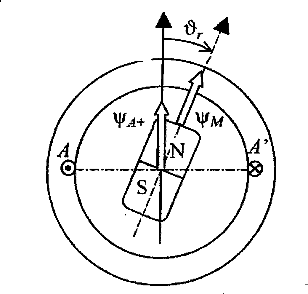
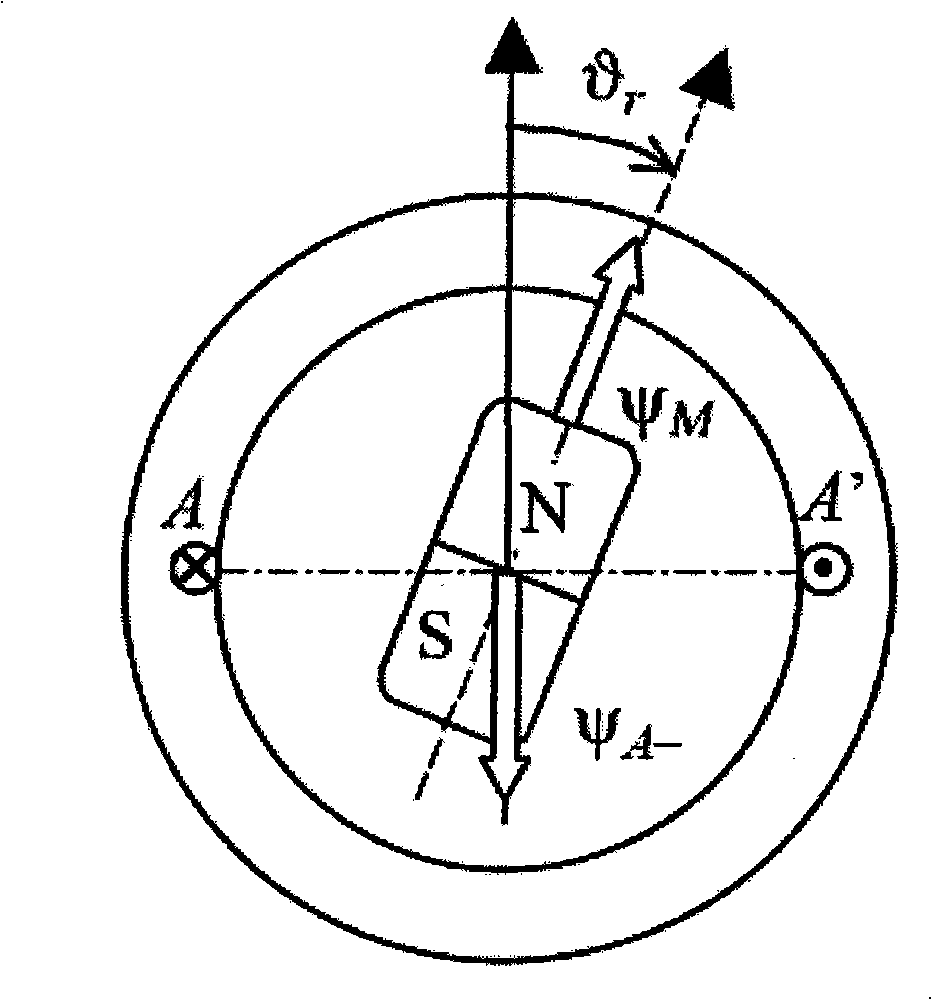
[0021] (1) In the permanent magnet synchronous motor, the rotor flux linkage can affect the flux linkage generated by the phase winding, such as figure 1 As shown, due to the saturation saliency effect, that is, when the flux linkage Ψ generated by the forward current A+ The direction of the rotor flux linkage Ψ M When the directions of the two are basically the same, the rotor flux linkage can increase the saturation degree of the stator core by affecting the phase winding (that is, the stator coil flux linkage), thereby reducing the inductance value of the phase winding; figure 2 As shown, when the reverse current produces Ψ A- The directi...


PUM


Abstract

The invention discloses a deduction method for the initial magnetic pole position of a permanent magnet synchronous motor, in which, firstly, when the elevator band brake is not switching-on, approximate initial magnetic pole position is calculated by the salient pole saturation effect and formula(1); then a vector transformation control is used, supposing an orthogonal shaft (D, Q) when the rotor magnetic linkage and force moment current position are not accurately known, supposing the setting of the Q shaft is zero, and meanwhile a D shaft current vector Id' twice of the motor rating current, constructing a position ring, according to the motor rotary direction after switching-on the band brake, countermovement on the setting current vector Id' direction allows the motor to quickly balance and static; finally the current vector (2) at this time is directly to the load to once more balancing, and then using the triangular theorem to obtain a formula (3), thereby requesting an actual motor load T'and an accurate motor magnetic pole position beta. The invention possesses the advantages of not only being capable of obtaining load values at the motor shaft terminal, but also being capable of more accurately testing the initial magnetic pole position, thereby the startup will be more comfortable and smoothing.

Description

Technical field: [0001] The invention relates to a method for inferring the initial magnetic pole position of a permanent magnet synchronous motor under rotor field orientation control. Background technique: [0002] At present, the vector control of the permanent magnet synchronous motor used in the elevator, that is, the field oriented control, generally adopts the control method of ID=0, that is, to make the rotor flux linkage generated by the permanent magnet of the rotor accurately positioned on the D axis of the vector control, Therefore, the comfort of the starting process of the permanent magnet synchronous motor and the stability of the control process are guaranteed. However, due to the randomness of the initial position of the rotor, if the magnetic pole position detection is not performed, it is difficult for the rotor flux to be accurately positioned on the D-axis when the motor is just started. When the rotor flux positioning deviation is large, it is easy to m...

Claims


Application Information

Patent Timeline
Patent Type & Authority Applications(China)
IPC IPC(8): H02P6/20H02P6/18H02P21/22H02P21/34
Inventor 张荣
Owner NINGBO HONGDA ELEVATOR
Why Eureka
Try Eureka