Method for operating hybrid drive system of hybrid vehicle and control device

A hybrid vehicle and hybrid drive technology, which is applied in the arrangement and engine control of multiple different prime movers of hybrid vehicles and general power units, can solve problems such as discarding, and achieve the effect of high starting efficiency.

Inactive Publication Date: 2020-02-14
ROBERT BOSCH GMBH
View PDF1 Cites 0 Cited by
  • Summary
  • Abstract
  • Description
  • Claims
  • Application Information

AI Technical Summary

Problems solved by technology

For safety reasons, the current calculated position is completely discarded after the combustion motor with "ignition off" is stopped

Method used


Image

  • Method for operating hybrid drive system of hybrid vehicle and control device
  • Method for operating hybrid drive system of hybrid vehicle and control device

Examples


Embodiment Construction

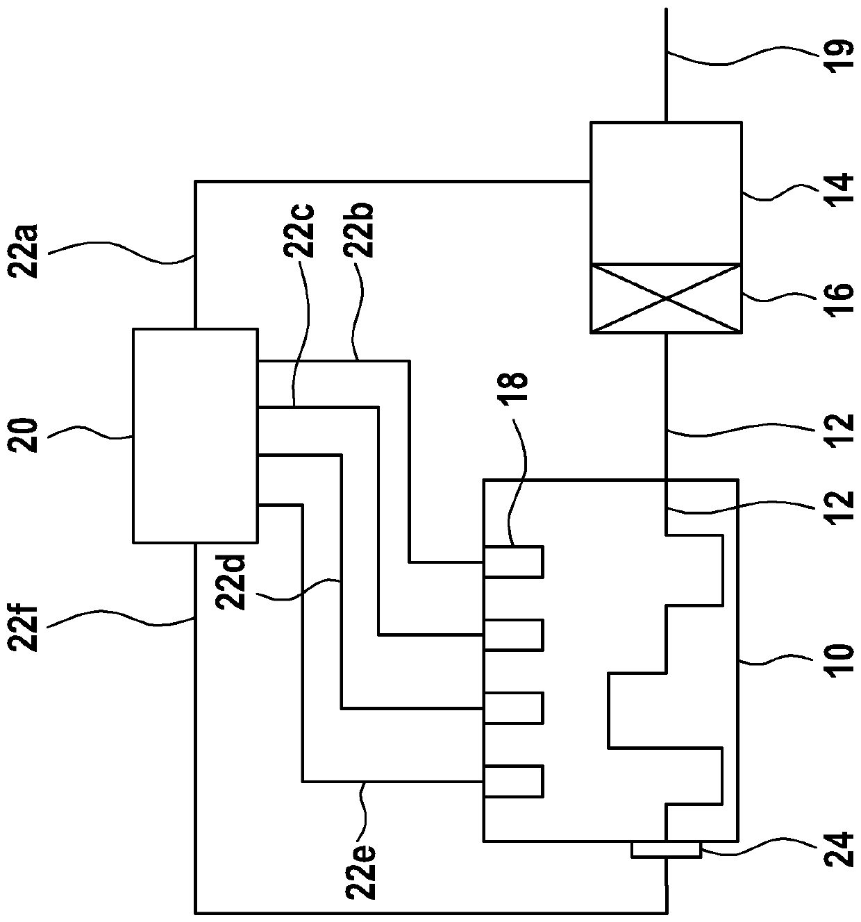
[0017] figure 1 A schematic diagram of a first hybrid drive system is shown for explaining an embodiment of a method for operating such a hybrid drive system.

[0018] exist figure 1 The hybrid drive system shown schematically in FIG. 2 comprises a combustion motor 10 with a cooperating crankshaft 12 and a drive electric machine 14 . Combustion motor 10 also has injection valves and ignition coils, not shown. By way of example only, the drive motor 14 is connected to the crankshaft 12 via a clutch 16 and / or a transmission, so that the crankshaft 12 can be rotated by means of the drive motor 14 and without the combustion motor 10 running. figure 1 The topology of the hybrid drive system can therefore also be referred to as the P2 topology. The rotation of the crankshaft 12 solely by means of the drive motor 14 is often also referred to as non-igniting rotation of the crankshaft 12 .

[0019] It is expressly pointed out, however, that the method described subsequently can al...


PUM


Abstract

The invention relates to a method for operating the hybrid drive system of a hybrid vehicle and a control device (20). According to at least one signal provided by one part of a hybrid vehicle (34), the start of the hybrid vehicle (34), which is static before the identification or prediction. During the operation period of the driving motor (14) of the hybrid drive system, through the rotation orlinkage of a crankshaft (12), the crankshaft (12) of the burning motor (10) of the hybrid drive system rotates to an initial position of the crankshaft (12) relative to the burning motor (10); from the moment when the crankshaft (12) exists on the initial position, the ejection valve an the ignition coil of the burning motor (10) can be controlled by the electronic device of the hybrid drive system to burn the burning motor (10); and after the hybrid vehicle (34) is started, the crankshaft (12) is rotated to the initial position.

Description

technical field [0001] The invention relates to a method for operating a hybrid drive system of a hybrid vehicle. Furthermore, the invention relates to a control device for a hybrid drive system of a hybrid vehicle and a hybrid drive system for a hybrid vehicle. Background technique [0002] EP 0 939 859 B1 describes a motor vehicle drive comprising a combustion motor and an electric machine. In order to start the combustion motor, the crankshaft and the camshaft, which is mechanically fixed to the crankshaft, are started to rotate by means of an electric motor, which is mechanically connected to the crankshaft. Not only on the crankshaft, but also on the camshaft are gear wheels with a special tooth profile, which are evaluated by sensors. At certain rotational angles, the crankshaft and camshaft reach positions in which a specific position can be determined by means of a special pattern on the corresponding sensor wheel. The injection and ignition of fuel can only be re...

Claims


Application Information

Patent Timeline
Patent Type & Authority Applications(China)
IPC IPC(8): F02N11/04F02N11/08F02N19/00
CPCF02N11/04F02N11/0829F02N11/0833F02N19/005B60K6/387B60K6/48B60K2006/4825B60W10/06B60W10/08B60W20/40B60W2510/0685B60W2510/244B60W2710/06B60W20/16F02D41/009F02D2041/0095F02D2250/24F02N11/0818F02N99/006Y02T10/40Y02T10/62
Inventor J.洛曼Y.策米什
Owner ROBERT BOSCH GMBH
Why Eureka
Try Eureka