Heat exchanger

A technology of heat exchangers and connectors, applied in the direction of heat exchanger types, indirect heat exchangers, heat exchange equipment, etc., can solve problems such as undesired mixing, and achieve better operation, avoid damage, and operate safely and efficiently. Effect

Inactive Publication Date: 2010-11-03
DANFOSS AS
View PDF1 Cites 1 Cited by
  • Summary
  • Abstract
  • Description
  • Claims
  • Application Information

AI Technical Summary

Problems solved by technology

There is therefore the possibility of the two media coming into contact with each other and mixing undesirably

Method used


Image

  • Heat exchanger
  • Heat exchanger
  • Heat exchanger

Examples


Embodiment Construction

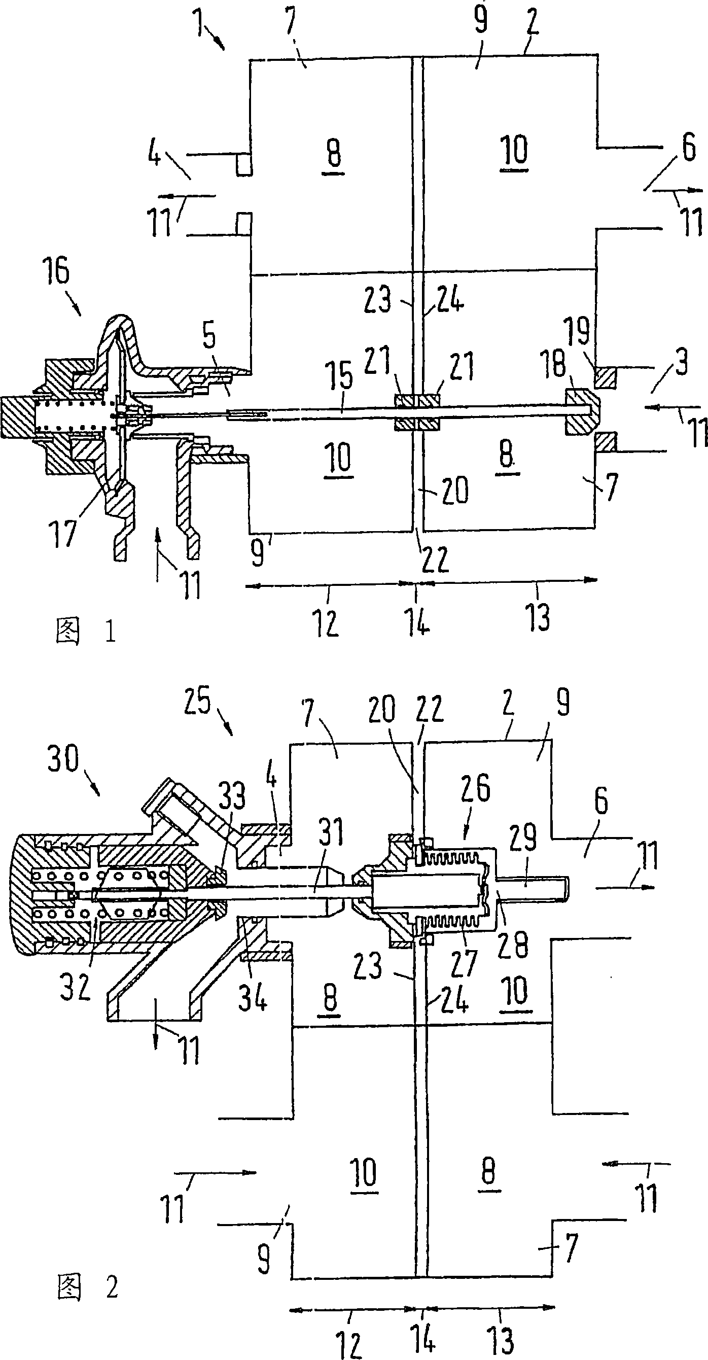
[0027] figure 1 A cross-sectional view of a heat exchanger 1 with a housing 2 with a primary inlet connector 3 , a primary outlet connector 4 , a secondary inlet connector 5 and a secondary outlet connector 6 is schematically shown. Between the primary inlet connector 3 and the primary outlet connector 4 the primary flow path 7 of the primary case 8 is arranged, and between the secondary inlet connector 5 and the secondary outlet connector 6 the secondary side 10 is arranged. Stage flow path9. exist figure 1In the sectional view of , the flow paths 7, 9 are only partially visible. The direction of flow is indicated by arrow 11 . Fluid from the primary side 8 enters at the primary inlet connector 3 and exits at the primary outlet connector 4 . Fluid from the secondary side 10 enters at the secondary inlet connector 5 and exits at the secondary outlet connector 6 . In the heat exchanger 1 , the fluid on the primary side 8 gives heat to the fluid on the secondary side 10 , s...


PUM


Abstract

The invention relates to a heat exchanger (1, 25, 35, 37) comprising a housing (2), with a primary inlet connector (3), a primary outlet connector (4), a secondary inlet connector (5), a secondary outlet connector (6), a primary flow path (7) between the primary inlet connector (3) and the primary outlet connector (4) on a primary side (8), a secondary flow path (9) between the secondary inlet connector (5) and the secondary outlet connector (6) on a secondary side (10), the primary flow path (7) being in heat-transferring connection to the secondary flow path (9). The heat exchanger (1, 25, 35, 37) comprises at least one control auxiliary device, arranged in the primary flow path (7) and the secondary flow path (9).; A constructive improvement to the heat exchanger is desirable which is achieved by means of running the control auxiliary device through a cavity (20), arranged between the primary flow path (7) and the secondary flow path (9).

Description

technical field [0001] The invention relates to a heat exchanger with a housing having a primary inlet connector, a primary outlet connector, a secondary inlet connector and a secondary outlet connector, where the primary inlet connector and the primary outlet are connected A primary flow path on the primary side is arranged between the connectors, and a secondary flow path on the secondary side is arranged between the secondary inlet connector and the secondary outlet connector, wherein the primary flow path is thermally connected to the secondary flow path , and the heat exchanger has at least one control auxiliary device arranged in the primary flow path and the secondary flow path. Background technique [0002] A heat exchanger of this type is known, for example, from EP 608 195 B1. A temperature sensor is integrated in the housing of the known heat exchanger and measures not only the temperature in the primary flow path but also the temperature in the secondary flow pa...

Claims


Application Information

Patent Timeline
Patent Type & Authority Patents(China)
IPC IPC(8): F28D9/00
CPCF28D9/005F28F27/00F28F3/005
Inventor 厄尔·赫多克林
Owner DANFOSS AS
Why Eureka
Try Eureka