Gear rack transmission type automatic locking device

An automatic locking, rack and pinion technology, used in building locks, building structures, building fastening devices, etc., can solve the problem that the automatic door closing function cannot be realized, the opening and closing are not flexible, and the stability of the cabinet is affected. and other problems, to achieve the effect of convenient opening and locking operation, flexible opening and closing, and solving the rebound of the cabinet door

Inactive Publication Date: 2010-12-15
哈尔滨飞云实业有限公司
View PDF9 Cites 3 Cited by
  • Summary
  • Abstract
  • Description
  • Claims
  • Application Information

AI Technical Summary

Problems solved by technology

[0003] In order to solve the problem that the lock on the existing file cabinet cannot realize the automatic door closing and locking function, and the existing locking mechanism has problems such as inflexible opening and closing, affecting the stability of the cabinet body during use, and high cost, the present invention further provides A rack and pinion automatic locking mechanism
[0005] The present invention has the following beneficial effects: the present invention realizes the closing and locking actions of the filing cabinet door at the same time, and solves the problem of the rebound of the cabinet door. The present invention has flexible opening and closing, good stability, and the opening and locking operations Advantages of convenience and low cost

Method used


Image

  • Gear rack transmission type automatic locking device
  • Gear rack transmission type automatic locking device
  • Gear rack transmission type automatic locking device

Examples


specific Embodiment approach 1

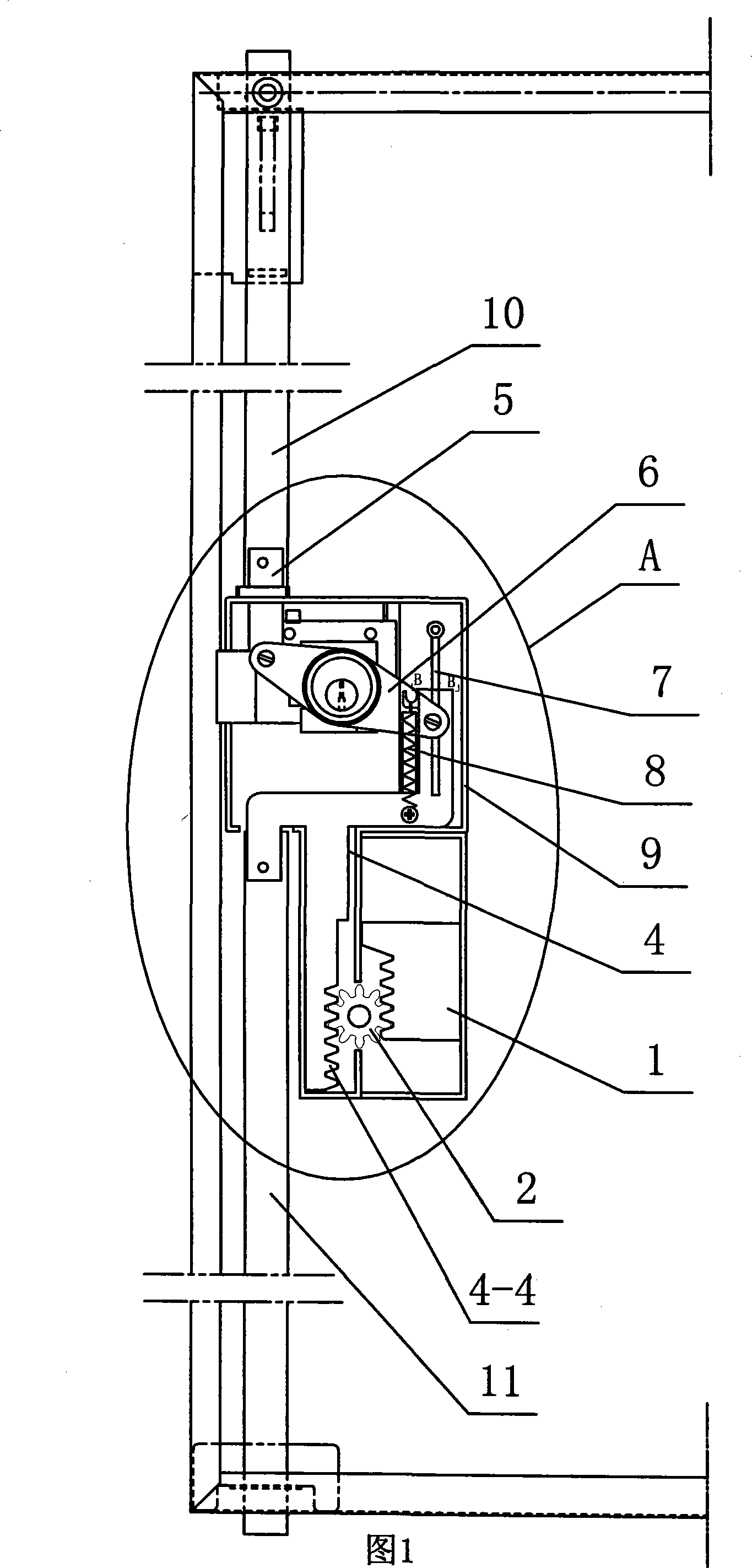
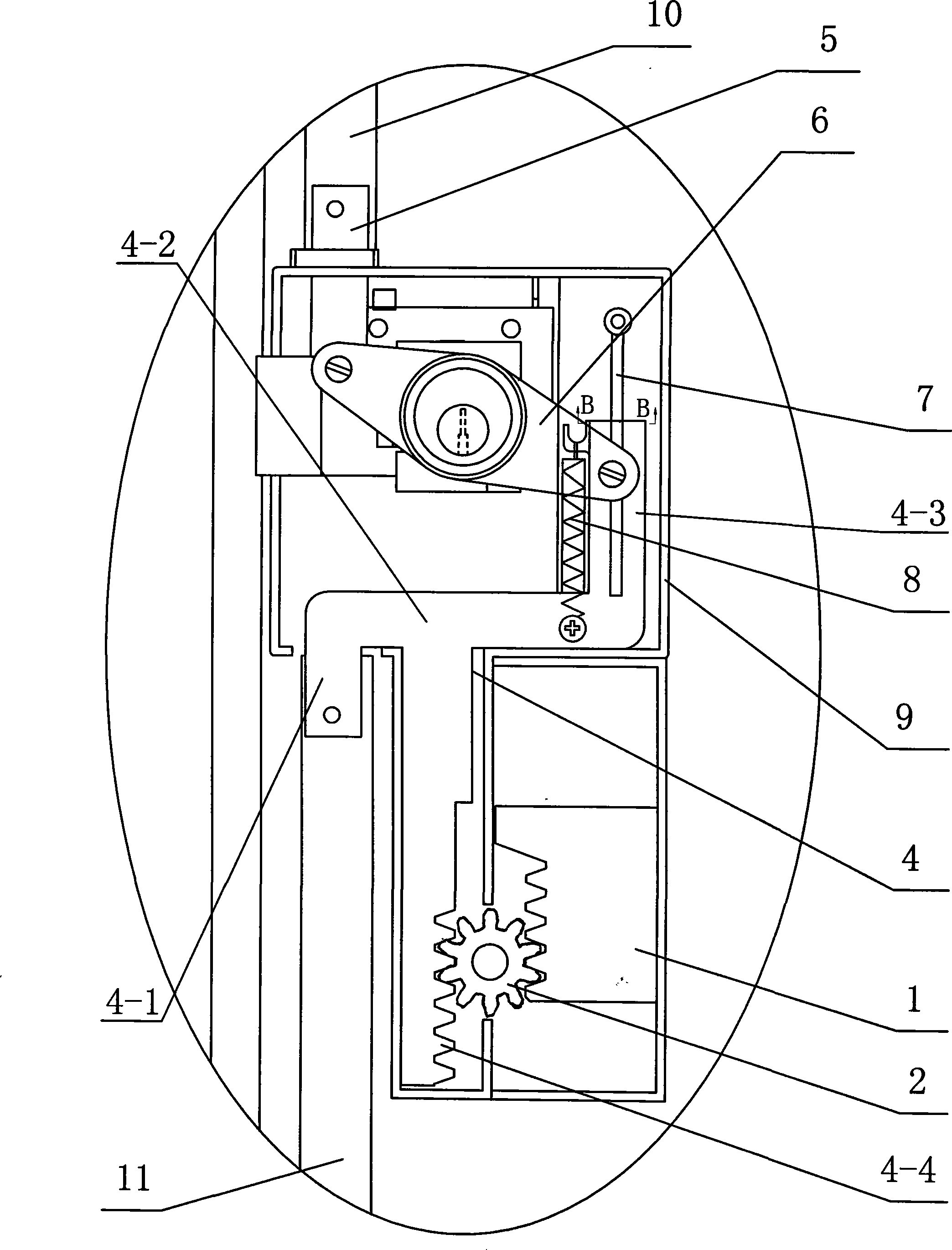
[0007] Specific implementation mode one: combine Figure 1-5 To illustrate this embodiment, the rack and pinion transmission type automatic locking mechanism in this embodiment includes a housing 9, a lock 6, an upper locking lever 10, a lower locking lever 11, and a touch button 15. The automatic locking mechanism also includes a mechanism Frame 4, hand rack 1, gear 2, upper connecting rod 5, energy storage elastic part 8, pulling rod 13; The lower end is connected, and the upper end of the upper connecting rod 5 passes through the housing 9, and the other end of the lockset 6 is connected with the upper end of the energy storage elastic member connecting rod 4-3 on the mechanism frame 4, and the rack bar 4-4 on the mechanism frame 4 The rack on the top meshes with one side of the gear 2, the gear 2 is mounted on the housing 9, the other side of the gear 2 meshes with the handle rack 1, and the upper end of the energy storage elastic member 8 It is connected with one side en...

specific Embodiment approach 2

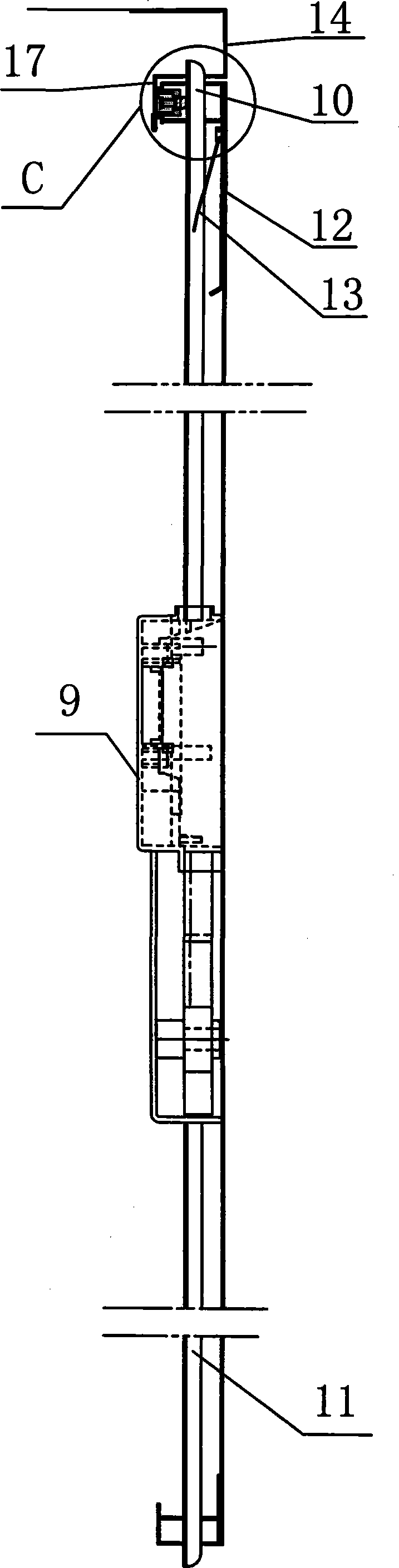
[0008] Specific implementation mode two: combination figure 1 with image 3 To illustrate this embodiment, the mechanism frame 4 of this embodiment is composed of a rack bar 4-4, a lower connecting rod 4-1, a horizontal rod 4-2, and an energy storage elastic member connecting rod 4-3. The horizontal rod 4 -2 Both ends are fixedly connected to the upper end of the vertically arranged lower connecting rod 4-1 and the lower end of the vertically arranged energy storage elastic member connecting rod 4-3, and the middle part of the horizontal bar 4-2 is connected to the vertically arranged rack bar 4 The upper end of -4 is affixed. So designed, easy to operate. Other components and connections are the same as those in the first embodiment.

specific Embodiment approach 3

[0009] Specific implementation mode three: combination figure 1 with image 3 To illustrate this embodiment, the rack bar 4-4, the lower connecting rod 4-1, the horizontal rod 4-2, and the connecting rod 4-3 of the energy storage elastic member described in this embodiment are integrated. Other components and connections are the same as those in the first embodiment.


PUM


Abstract

The invention discloses a gear and rack driving type automatic locking mechanism, relating to a locking mechanism used for a file cabinet. The invention resolves the problems that the prior lock on the file cabinet can not realize the functions of automatic closing and locking, the prior locking mechanism is dumb when unlocked and locked. One end of a lock (6) is connected with the lower end of an upper connecting rod (5), the upper end of the upper connecting rod (5) penetrates a casing (9), the other end of the lock (6) is connected with a mechanism support (4), gears (2) and racks on a rack lever (3) are meshed, the gears (2) are meshed with hand pulling racks (1), an energy storage elastic part is connected with an energy storage elastic part connecting rod (4-3), and the lower end ofthe energy storage elastic part (8) is fixed on the casing (9). The gear and rack driving type automatic locking mechanism realizes that the door of the file cabinet can be closed and locked at the same time, and solves the problem of the rebounding of the cabinet door. The gear and rack driving type automatic locking mechanism has the advantages of flexible unlocking and locking, excellent stability, low cost and convenient unlocking and locking.

Description

technical field [0001] The invention relates to a locking mechanism for filing cabinets. Background technique [0002] Existing steel filing cabinets (iron cabinets) generally adopt manual methods such as picking hands or keys to open and close the cabinet door, and the lockset on the filing cabinet itself cannot realize the automatic door closing and locking function. If you want to automatically lock the cabinet door, it is generally realized by using an external force closing structure such as a closer (locking mechanism), but this increases the cost of the lock on the one hand, and the opening and closing of the cabinet door is not flexible enough; The general steel filing cabinet products are often not very firm in structure. If an external force closer is used, the stability of the cabinet will be affected. Contents of the invention [0003] In order to solve the problem that the lock on the existing file cabinet cannot realize the automatic door closing and locking...

Claims


Application Information

Patent Timeline
Patent Type & Authority Patents(China)
IPC IPC(8): E05B63/14E05B65/52E05C9/04
Inventor 赵明俭
Owner 哈尔滨飞云实业有限公司
Why Eureka
Try Eureka